Page 13
6.2 – REAR PANEL
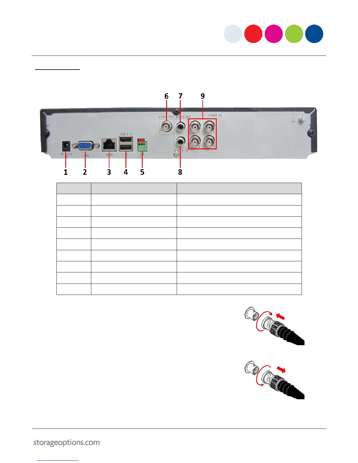
Refer to the diagram and table below for information on the DVR’s various connections.
Connect to a monitor with VGA (D-Sub) input
Connect to a computer network
For USB flash drive (top) and mouse (bottom)
Connect to a TV or monitor (BNC)
Connect audio output (phono)
Connect audio input (phono)
4x numbered video inputs for cameras (BNC)
To connect a camera via BNC:
1. Align the BNC connector with the notches on the BNC socket and
slide into place.
2. Rotate the BNC connector clockwise until it locks in place.
To disconnect a camera:
1. Apply pressure to the BNC connector, then rotate anti-clockwise.
2. Slide the BNC connector away from the socket.