20
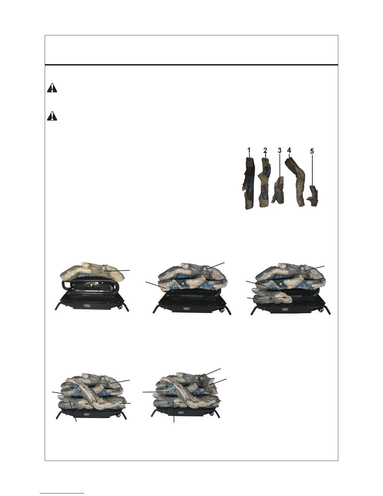
INSTALLING LOGS
WARNING: Failure to position the parts in accordance with these diagrams or
failure to use only parts specically approved with this heater may result in property
damage or personal injury.
CAUTION: After installation and periodically thereafter, check to ensure that no
Provided Logs: 5
1. Insert
log #1 into slots in
rear log bracket on grate
base, and tighten nuts.
Figure 26 - Installing Log #2
Figure 27 - Installing Log #3
Figure 28 - Installing Log #4 Figure 29 - Installing Log #5
1
2
5
3
4
5. I
nsert the recessed hole on
the bottom of log #5 onto
pin on log #1, with the other
end placed on log #2.
4. Insert log #4 into slots in
front log bracket on grate
base and tighten nuts.
4
3
1
2
1
2
3
3.
Insert log #3 into slots in
front log bracket on grate
base and tighten nuts.
1
2
2. I
nsert log #2 into slots in
middle grate bracket and
tighten nuts.
Figure 25 - Installing Log #1
1
24 IN. VENT-FREE GAS LOGS
yellow ames contact any log. If so, reposition
logs according to the log installation instructions
in this manual. Yellow ames contacting logs will
create soot.
It is very important to install the logs exactly as
instructed. Do not modify logs. Use only logs
supplied with heater.
Each log is marked with a number. This number
will help you to identify the logs when installing.
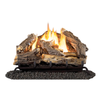
After installing logs, add decorative cinders
around the grate base, do not place any
decorative cinders on logs or burner.