29
INSPECTING BURNERS
Check pilot ame pattern and burner ame patterns often.
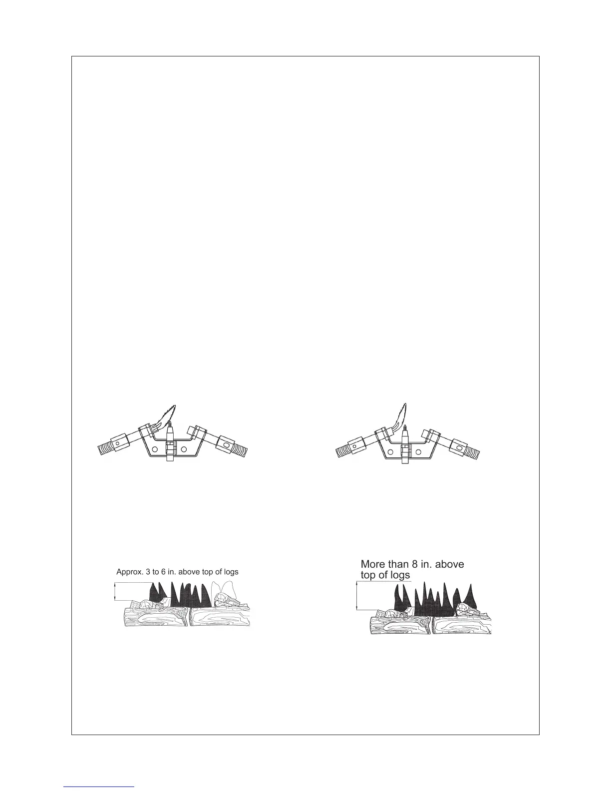
PILOT FLAME PATTERN
Figure 50 shows a correct pilot ame pattern. Figure 51 shows an incorrect pilot ame
pattern. The incorrect pilot ame is not touching the thermocouple. This will cause he
thermocouple to cool. When the thermocouple cools, the heater will shut down.
If pilot ame pattern is incorrect, as shown in Figure 51:
Turn heater off (see “To Turn Off Gas To Appliance”).
See Troubleshooting, page 3
1.
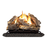
BURNER FLAME PATTERN
Figure 52 shows a correct burner ame pattern. Figure 53 shows an incorrect burner
ame pattern. If burner ame is incorrect, as shown in Figure 53:
Turn heater off.
See Troubleshooting, page 3
1.
•
•
•
•
Figure 53– Incorrect Flame Pattern with
Control Knob Set to High Flame
Figure 50 – Correct Pilot Flame Pattern
Figure 5
1– Incorrect Pilot Flame Pattern
Figure 52– Correct Flame Pattern with
Control Knob Set to High Flame
MATCHING SECURITY CODES
Program the remote receiver to LEARN a new scurity code by pushing in the LEARN
button the top of the remote receiver and then pressing any button on the transmitter.
NOTE: This equipment has been tested and found to comply with the limits for Class B
digital device, pursuant to part 15 of the FCC Rules. These limits are designed to provide
reasonable protection against harmful interference in a residential installation.This
equipment generates, uses and can radiate radio frequency energy and, if not installed
and used in accordance with the instructions, may cause harmful interference to radio or
television reception, which can be determined by turning the equipment off and on, the
user is encouraged to try to correct the interference by one or more of the following
measures:
• Reorient or relocate the receiving antenna.
• Increase the separation between the equipment and the receiver.
• Connect the equipment into an outlet on a circuit different from that to which the
receiver is connected.
• Consult the dealer or an experienced radio/TV technician for help.