Component Access/Removal
Model 315I (UC Ice Maker)
5-8
#3757320 - Revision B - August, 2005
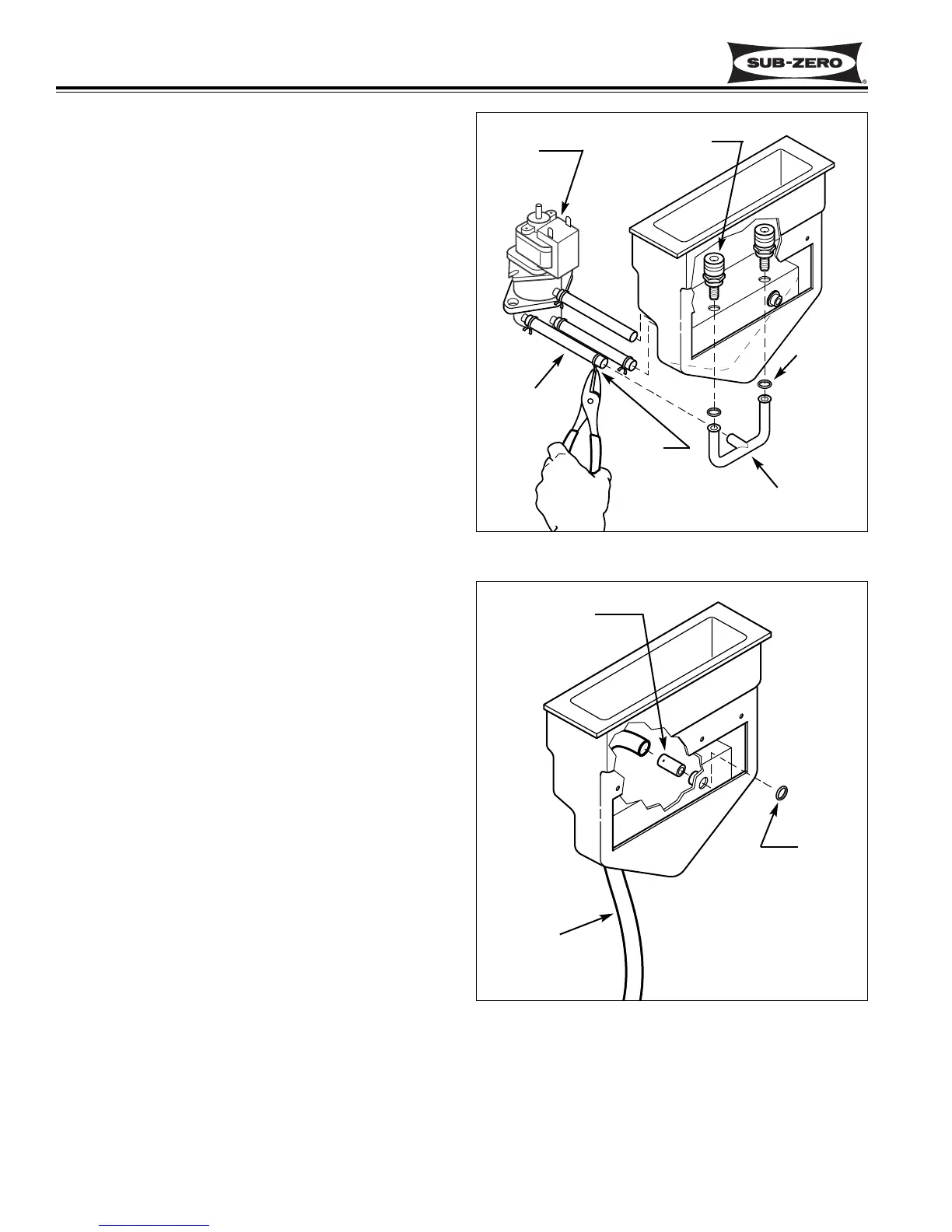
O-Ring and Spray Bar Assembly Removal
The spray bar is a copper tubing assembly with one
inlet port and two outlet ports. The inlet fits inside the
circulating/spray pump discharge tube. An O-ring is
positioned at the top of each spray bar outlet port. The
jet base stems pass down through the reservoir wall
and the O-rings and then screw into the outlet ports,
sandwiching the O-rings which seal the connection.
NOTE: The use of a mirror will help in the following
removal procedures.
To remove an O-ring, extract the appropriate jet base
and pull the O-ring from the top of the spray bar tubing.
To remove the spray bar assembly, extract both spray
jet assemblies or jet bases and remove the O-rings.
With a pliers, depress the ends of the hose clamp at the
spray bar inlet and pull the spray bar from the the circu-
lating/spray pump discharge tube. (See Figure 5-15)
Circulating/Spray Pump Hose Removal
There are three hoses connected to the circulating
spray pump nipples. The bottom hose is the pump inlet
hose, leading from the reservoir bottom nipple. The
second hose up is the spray discharge hose leading to
the spray bar assembly. The top hose on the pump
leads to the top center reservoir nipple. The purpose of
the top discharge hose is to bypass the spray discharge
hose if it were to become clogged or air-locked.
NOTE: The use of a mirror will help in the following
removal procedures.
To remove a pump hose, depress the ends of the hose
clamp on the hose and pull the hose off of the nipples
and/or spray bar assembly. (See Figure 5-15)
Reservoir Drain Hose Removal
The reservoir drain hose fits between the top right
reservoir nipple and the ice bin drain fitting.
NOTE: The use of a mirror will help in the following
removal procedures.
To remove the drain hose, pull it off of the top right
reservoir nipple and the drain fitting. (See Figure 5-16)
O-Ring and Stainless Steel Drain Nipple Removal
The stainless steel drain nipple is inserted through the
back of the top right reservoir nipple, up to the nub on
the nipple. An O-ring is then placed over the stainless
nipple inside the reservoir.
NOTE: The use of a mirror will help in the following
removal procedures.
To remove the stainless steel nipple, the drain hose
must be removed from the top right reservoir nipple
first. Then, remove the O-ring inside the reservoir and
pull the stainless steel nipple out through the back of
the reservoir top right nipple. (See Figure 5-16)
Spray Bar
Assembly
O-Ring
Hoses
Circulating/Spray
Pump
Hose
Clamp
Spray Jet
Assembly
Figure 5-15. O-Ring, Spray Bar and Hose Removal
O-Ring
Drain
Hoses
S.S.
Nipple
Figure 5-16. Drain Hose, O-Ring & SS Nipple
Removal