Component Access/Removal
Model 315I (UC Ice Maker)
5-14
#3757320 - Revision B - August, 2005
Evaporator Assembly Removal
The evaporator assembly consists of the evaporator,
heat exchanger assembly and hot gas line from the gas
valve. The evaporator/cube mold sits inside the top of
the reservoir insert. The evaporator/platen cover is
placed over the evaporator and a piece of tape is
placed over the cover to keep it in place.
To access the evaporator assembly, remove the control
panel, inner access panel, upper and lower face plates,
back panel, unit shell, insulation bag, tube retaining clip
and evaporator/platen cover.
Before removing the evaporator assembly, capture the
refrigerant from the sealed system. Then, use a file to
score and separate the capillary tube approximately
one inch from the filter-drier. Use a tube cutter to cut
the suction line approximately one inch from the com-
pressor. Cut the hot gas line approximately one inch
from the hot gas valve and lift the assembly out of the
reservoir insert and off of the back of the bin assembly.
(See Figure 5-29)
Hot Gas Valve Removal
The inlet of the hot gas valve is attached to a “T” con-
nection off of the compressor discharge line. The outlet
of the valve is attached to the hot gas line that runs up
to the evaporator. The hot gas solenoid coil is attached
to the top of the hot gas valve body with a clip.
To access the hot gas valve, remove the control panel,
inner access panel, upper and lower face plates, back
panel and unit shell.
NOTE:: Separating the top of the base assembly from
the bottom by extracting the screws from the base
assembly legs will allow easier access to the hot gas
valve.
Before removing the hot gas valve, capture the refriger-
ant from the sealed system. Then, disconnect the sole-
noid coil from the valve body. With a a tube cutter, cut
the valve inlet and outlet tubing approximately one inch
from the valve body and lift the valve off of the base
assembly. (See Figure 5-30)
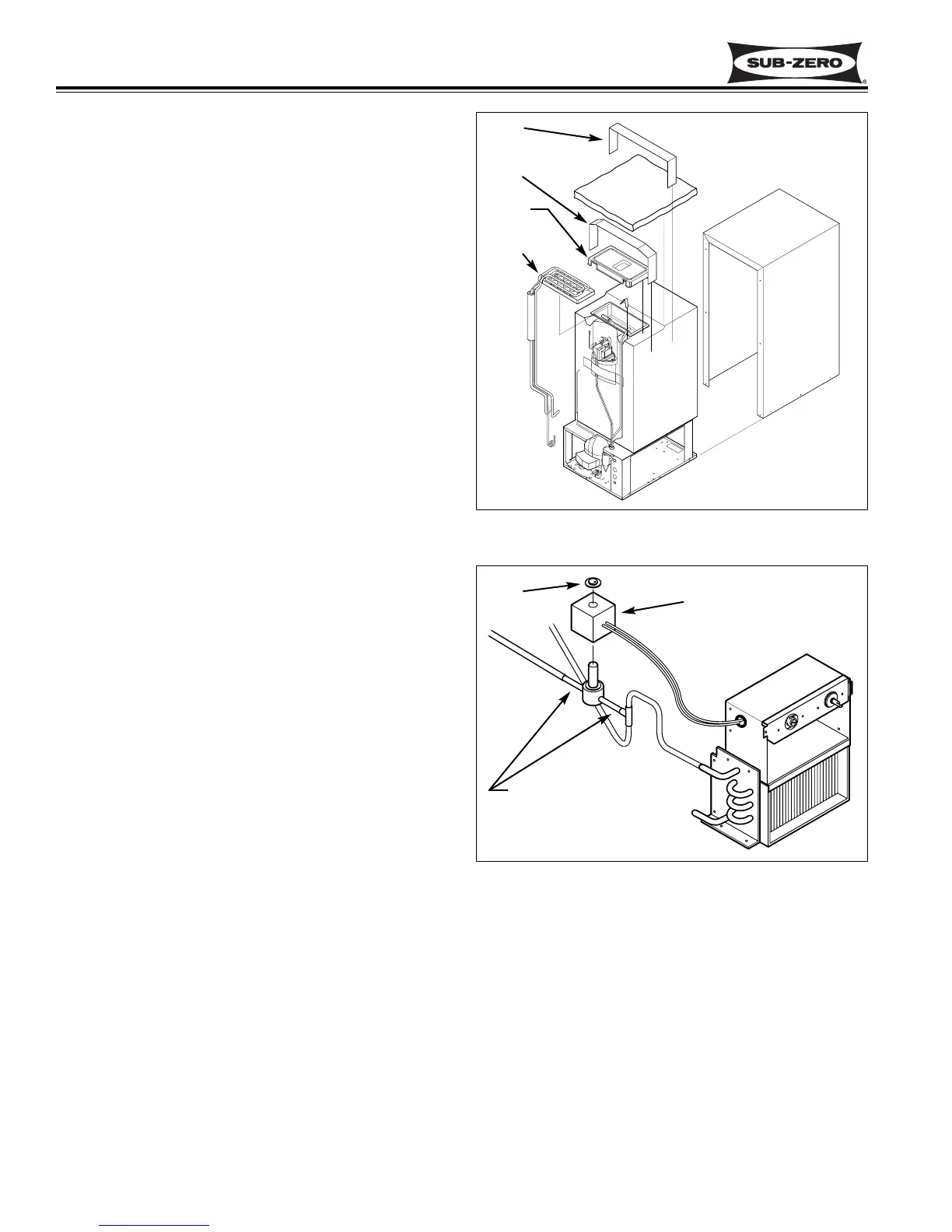
Figure 5-29. Evaporator Assembly Removal
Tape
Tape
Cover
Insulation
Shell
Evap. Assy
Figure 5-30. Hot Gas Valve Removal
Clip
Solenoid Coil
Cut inlet and outlet tubes
approximately 1” from
hot gas valve body.