Model 315I (UC Ice Maker)
Component Access/Removal
5-11
#3757320 - Revision B - August, 2005
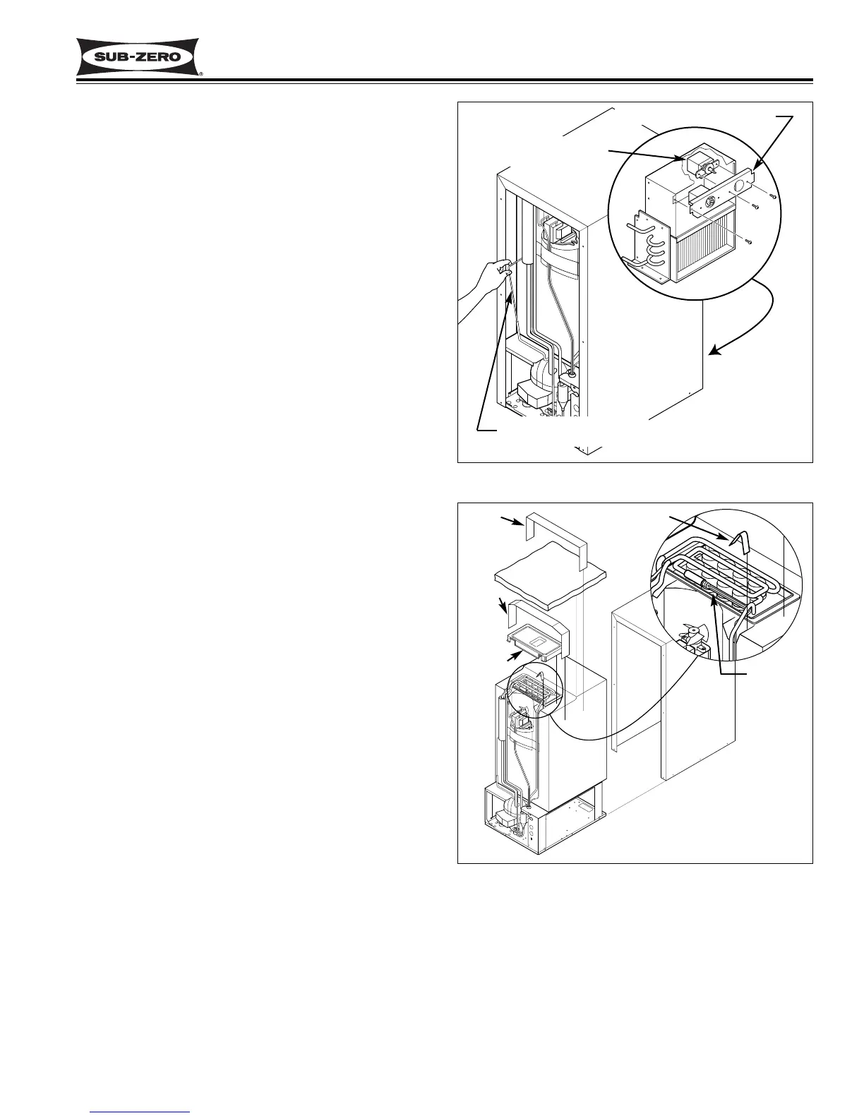
Figure 5-23. Bin Level Control Removal
Bin Level Control
Control Box Face Plate
Control Capillary Tube
Bin Level Control (Thermostat) Removal
The bin level control is mounted to the right side of the
control box face plate with screws. Two wires are con-
nected to the back of the control. The control capillary
tube is inserted into a plastic sleeve and routed out the
back of the control box, up through a grommet in the
base assembly, up the back of the bin assembly and
into the back of the cylindrical bin thermostat bracket.
To access the bin level control, remove the control
panel, inner access panel and back panel.
Before removing the bin level control, disconnect the
power to the unit. Then, extract the control box face
plate mounting screw and pull the face plate forward.
Extract the control mounting screws. Disconnect the
electrical leads from the control. At the back of the unit,
pull the control capillary tube from the thermostat brack-
et, then pull the capillary tube with the sleave from the
grommet in the base assembly. At the front of the unit,
pull the control body, capillary tube and sleeve forward,
out of the control box. (See Figure 5-23)
Cube Size Control (Evap. Thermostat) Removal
The cube size control is mounted to the left side of the
control box face plate with screws. Three wires are
connected to the back of the control. The control capil-
lary tube is routed out the back of the control box, up
through a grommet in the base assembly, up the back
of the bin assembly, then inserted into a tube attached
to the evaporator.
To access the cube size control, remove the control
panel, inner access panel, upper and lower face plates,
back panel, unit shell, insulation bag, tube retaining clip
and evaporator/platen cover.
Before removing the cube size control, disconnect the
power to the unit. Then, extract the control box face
plate mounting screw and pull the face plate forward.
Extract the control mounting screws. Disconnect the
electrical leads from the control. At the back of the unit,
pull the control capillary tube from the tube on the evap-
orator, then pull the capillary tube from the grommet in
the base assembly. At the front of the unit, pull the con-
trol body and capillary tube forward, out of the control
box. (See Figure 5-24)
Figure 5-24. Cube Size Control Removal
Tape
Tape
Cover
Insulation
Shell
Retaining Clip
Capillary
Tube