Model 315I (UC Ice Maker)
Component Access/Removal
5-9
#3757320 - Revision B - August, 2005
COMPONENTS BEHIND PANELS AND
SHELL
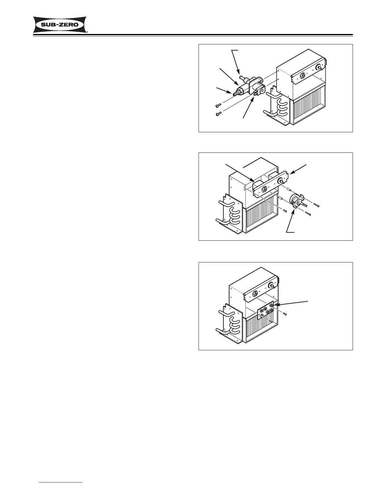
Inlet Water Valve Removal
The inlet water valve is attached to the left side of the
control box with screws. The inlet and outlet water lines
are connected to the valve with compression fittings.
To access the inlet water valve, remove the control
panel and inner access panel.
Before removing the water valve, shut off the water
supply and disconnect power to the unit. Then, unplug
the valve electrical leads. With a wrench, disconnect
the inlet water line from the valve. Extract the valve
mounting screws, pull the valve forward and disconnect
the outlet water line. (See Figure 5-17)
Harvest Cycle Timer & Switch Removal
The harvest cycle timer switch is attached to the timer.
The timer is attached inside the control box with screws
and spacers. Three wires are connected to the switch.
One electrical lead from the timer runs to the terminal
board, the other runs to the cube size control.
To access the cycle timer, remove the control panel and
inner access panel.
Before removing the harvest cycle timer and switch,
disconnect the power to the unit. Then, unplug the
electrical leads from the switch. Extract the timer
mounting screws and pull the timer forward.
Disconnect the timer electrical lead from the terminal
board. Extract the control box face plate mounting
screw, pull the face plate forward and disconnect the
timer electrical lead from the cube size control. (See
Figure 5-18)
Terminal Board Removal
The terminal board is attached inside the control box
with screws.
To access the terminal board, remove the control panel,
inner access panel and lower face plate.
Before removing the terminal board, disconnect power
to the unit. Then, extract the board mounting screws,
disconnect all electrical leads from the terminal board
and pull the board forward. (See Figure 5-19)
Figure 5-17. Water Valve Removal
Valve
Valve
Electrical Plug
Outlet
Inlet
Figure 5-18. Cycle Timer Removal
Cycle Timer
Control
Face Plate
Ice Thickness
Control
Figure 5-19. Terminal Board Removal
Terminal
Board