Section 2
DESCRIPTION
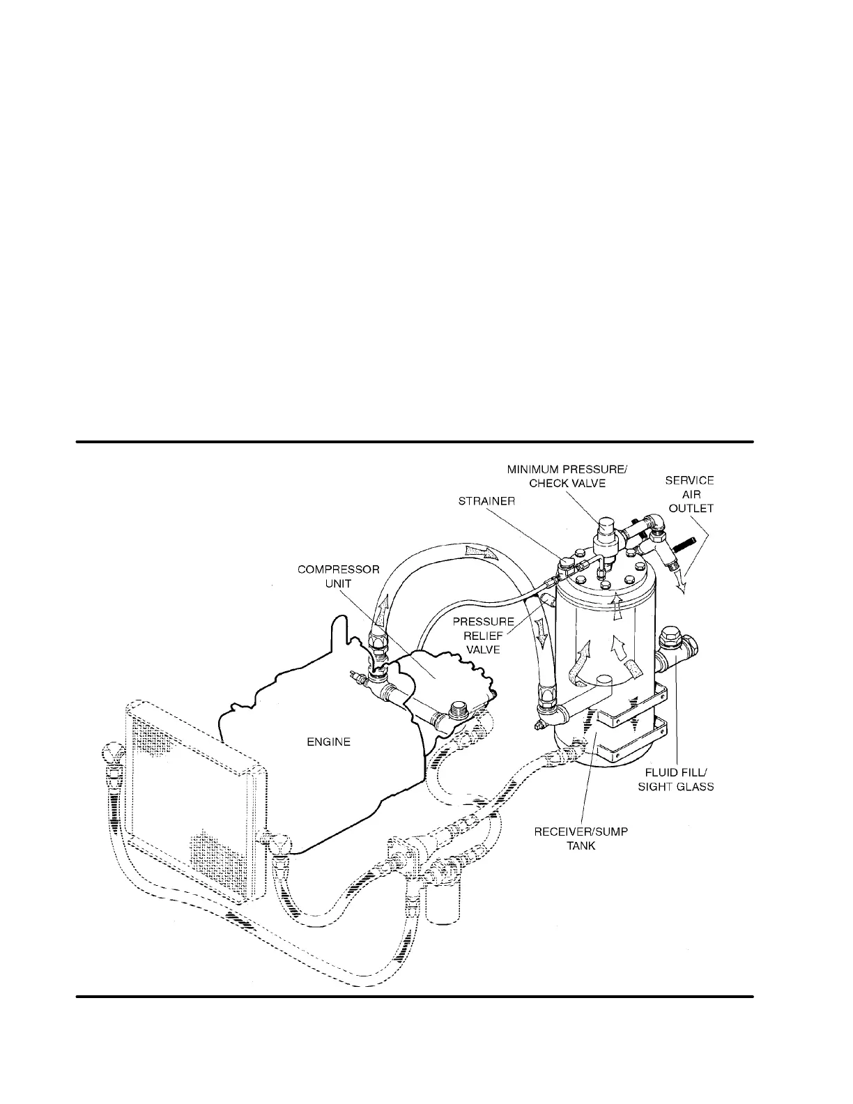
11
2.6 CAPACITY CONTROL SYSTEM, FUNCTIONAL
DESCRIPTION
Refer to Figure 2---3 and 2---4. The purpose of the
control system is to regulate the amount of air intake
in accordance with the amount of compressed air
being used. The control system consists of a
pressure regulating valve(s), air inlet valve, sys-
tem blowdown valve, and hoses connecting the
various components to the compressor and en-
gine governor. The functional descriptions of the
control s ystem are given in four distinct phases of
operation. It applies to any control system with the
exception of those with stated pressures which are
dependent on pressure requirements. The pres-
sures stated will be in accordance with a compres -
sor having an operating pressure range of 100 to
110 psig (6.9 to 7.6bar).
START -- 0 TO 40 PSIG (0 to 2.8 BAR)
COLD START
When the compressor is started, the sump pressure
will quickly rise from 0 to 40 psig (0 to 2.8 bar). Dur-
ing this period the pressure regulator valve is inac-
tive. At this pressure range the idle warm---up valve
maintains a closed inlet valve for engine idle opera-
tion. After sufficient machine warm---up is achieved,
push the idle warm---up valve button on the instru-
ment panel. The inlet valve is fully open due to inlet
air pressure, and the compressor operates at full ca-
pacity operation. As the compressor operates at full
capacity, the engine runs at full speed.
NORMAL OPERATION -- 55 TO 100 PSIG (3.8 TO
6.9 B AR) OR 55 TO 150 PSIG (3.8 TO 10.3 BAR)
FOR “H” MACHINES
When the sump pressure rises a bove 55 psig (3.8
bar), the minimum pressure valve opens and deliv-
ers compressed air to the service line. At t his time,
Figure 2 ---3 Compressor Discharge System