32
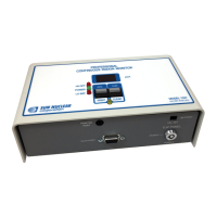
Figure 6-1. Connectors, Controls, and Indicators
Thermal Printer
12 Yellow LED Function indicator. Normally off. When Model 1027 is powered
up, LED flashes twice, followed by a single flash, indicating
startup test is complete and unit is functioning normally. During
monitoring, yellow LED flashes each time an alpha particle is
detected. Flashes rapidly if Model 1027 fails during monitoring.
When buttons are in PRINT/CLEAR mode, yellow LED is
flashing. In this mode:
• When PRINT is pressed, yellow LED turns on. When PRINT is
released, LED turns off and data transfer begins. When data
transfer is complete, yellow LED flashes once.
• When CLEAR is pressed, yellow LED turns off. Hold down un-
til yellow LED turns on again; then release. Yellow LED and
display LEDs flash once followed by a single flash of yellow
LED. Model 1027 memory is cleared.
13 LO BAT When red LED is on, battery has about two hours of life
remaining. Power adapter must be unplugged for LO BAT test.
14 POWER Green LED is on continuously when Model 1027 is powered by
mains power; flashes when powered by batteries only; off
when LO BAT is on.
15 HV OFF Red LED is normally off. When on, High Voltage circuit is off,
indicating Model 1027 has failed. See Thermal Printer
Maintenance on page 22.
16 Battery
compartment
A single 9-volt alkaline battery is used for Model 1027 power
backup. Battery is NOT recharged by Model 1027. A fresh
battery will operate Model 1027 for approximately 20 hours.
17 Power
connector
Power adapter should be plugged into Model 1027 BEFORE
adapter is plugged into mains power.
Table 2. Thermal Printer Indicators
Indicator Means
Green POWER • Flashing 1x/sec. – power on.
• Flashing 1x/.5 sec.– battery low.
Green ON LINE • Flashing – there is data in buffer memory when switch is tog-
gled to OFF LINE.
Red OFF LINE • On steady – Paper feed possible.
• Flashing – paper is not set or has run out.
Green ON LINE
Red OFF LINE
Both flashing – there is an error.
No. Description Function