44 Function Parameter Table
E500 Series Universal Low-Power Inverter
0: Inverter is running
When the inverter is running, it outputs effective signals, and when the inverter
is at stop, it outputs void signals.
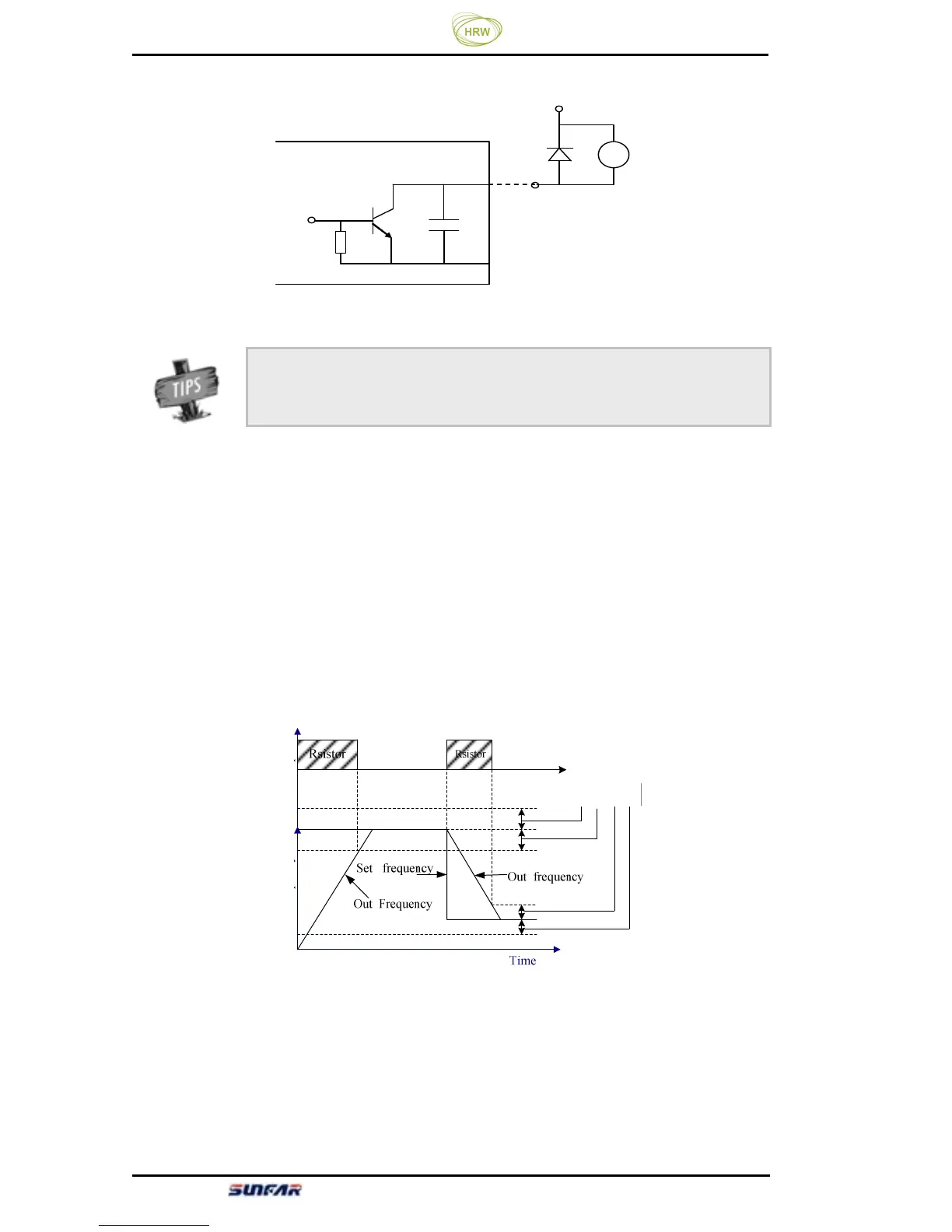
1: Frequency reaching
When the inverter’s output frequency is approaching the set frequency within
certain range (which is defined by parameter [F1.17]), it outputs effective signals,
otherwise, it outputs void signals.
2: Frequency level detection (FDT)
When the inverter’s output frequency exceeds FDT frequency level, after the set
delay time, it outputs effective signals. When the inverter’s output frequency is
lower than the FDT frequency level, after the same delay time, it outputs void
R
1
2
D
Figure 6-8 internal circuit of OC output terminal
Figure 6-9 Frequency reaching signal
For connecting external inductive elements (e.g. relay coil),
freewheel diode D must to be connected in parallel.
Frequency
Port output
[F1.17]