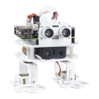
SunFounder 3in1 Kit
(continued from previous page)
}
}
Notes and Warnings
• Looking closely at the R4 board, the pins marked with the “~” symbol have analog output function.
• The PWM outputs generated on pins 5 and 6 will have higher-than-expected duty cycles. This is because of
interactions with the millis() and delay() functions, which share the same internal timer used to generate
those PWM outputs. This will be noticed mostly on low duty-cycle settings (e.g. 0 - 10) and may result in a
value of 0 not fully turning off the output on pins 5 and 6.
Related Components
Below are the related components, you can click in to learn how to use them.
4.2.1 2.1 Fading
This project is similar to 1.1 Hello, LED! , the difference is the signal type. The former is to make the LED light on
or off by outputting a digital signal (0&1), this project is to control the brightness of the LED by outputting an analog
signal.
Required Components
In this project, we need the following components.
It’s definitely convenient to buy a whole kit, here’s the link:
Name ITEMS IN THIS KIT LINK
3 in 1 Starter Kit 380+
You can also buy them separately from the links below.
COMPONENT INTRODUCTION PURCHASE LINK
Arduino Uno R4 Minima -
Breadboard
Jumper Wires
Resistor
LED
Schematic
4.2. 2. Analog Write 97