SunFounder 3in1 Kit
1.6 Jumper Wires
Wires that connect two terminals are called jumper wires. There are various kinds of jumper wires. Here we focus on
those used in breadboard. Among others, they are used to transfer electrical signals from anywhere on the breadboard
to the input/output pins of a microcontroller.
Jump wires are fitted by inserting their “end connectors” into the slots provided in the breadboard, beneath whose
surface there are a few sets of parallel plates that connect the slots in groups of rows or columns depending on the
area. The “end connectors” are inserted into the breadboard, without soldering, in the particular slots that need to be
connected in the specific prototype.
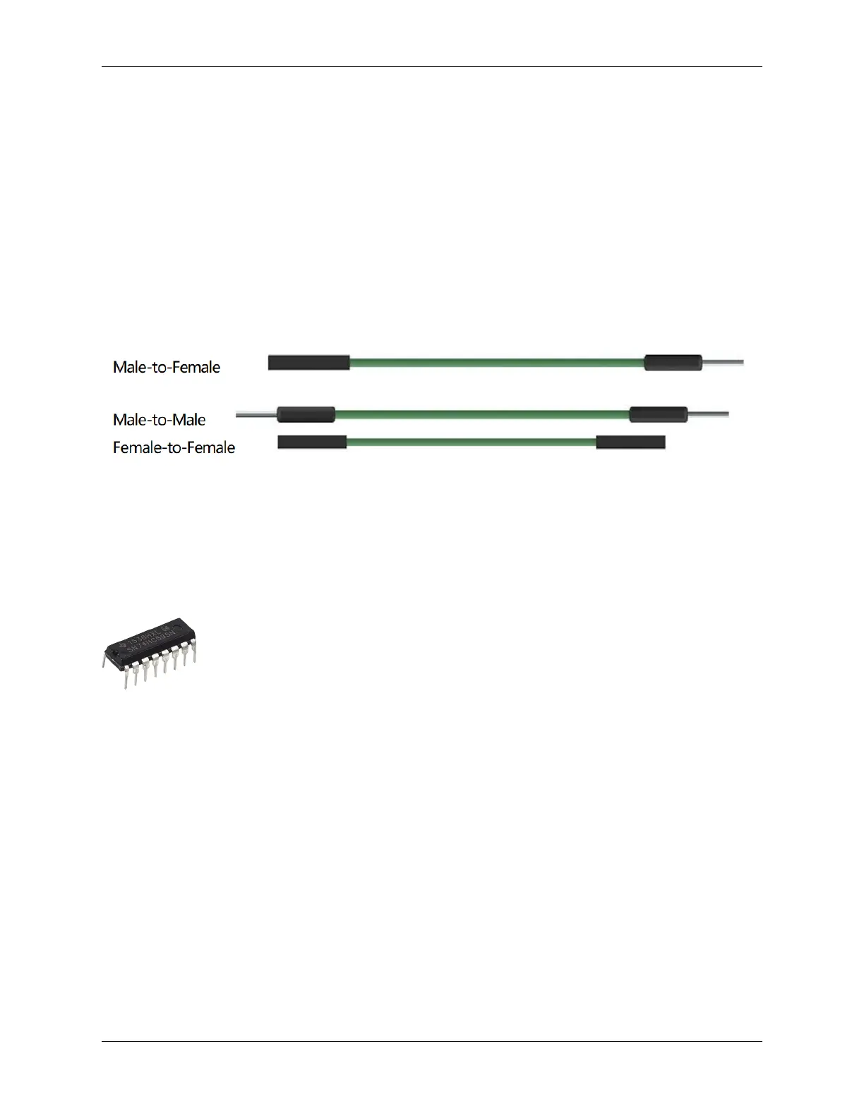
There are three types of jumper wire: Female-to-Female, Male-to-Male, and Male-to-Female. The reason we call it
Male-to-Female is because it has the outstanding tip in one end as well as a sunk female end. Male-to-Male means
both side are male and Female-to-Female means both ends are female.
More than one type of them may be used in a project. The color of the jump wires is different but it doesn’t mean their
function is different accordingly; it’s just designed so to better identify the connection between each circuit.
Chip
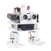
1.7 74HC595
The 74HC595 consists of an 8bit shift register and a storage register with threestate parallel outputs. It converts serial
input into parallel output so you can save IO ports of an MCU. When MR (pin10) is high level and OE (pin13) is low
level, data is input in the rising edge of SHcp and goes to the memory register through the rising edge of SHcp. If the
two clocks are connected together, the shift register is always one pulse earlier than the memory register. There is a
serial shift input pin (Ds), a serial output pin (Q) and an asynchronous reset button (low level) in the memory register.
The memory register outputs a Bus with a parallel 8-bit and in three states. When OE is enabled (low level), the data
in memory register is output to the bus.
• 74HC595 Datasheet
16 Chapter 1. Components List and Introduction