SunFounder 3in1 Kit
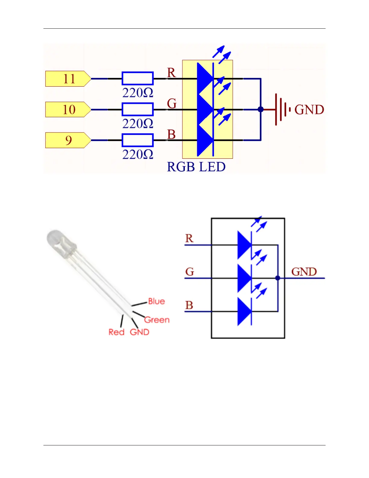
The PWM pins 11, 10 and 9 control the Red, Green and Blue pins of the RGB LED respectively, and connect the
common cathode pin to GND. This allows the RGB LED to display a specific color by superimposing light on these
pins with different PWM values.
Wiring
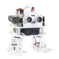
An RGB LED has 4 pins: the longest pin is the common cathode pin, which is usually connected to GND, the left pin
next to the longest pin is Red, and the 2 pins on the right are Green and Blue.
4.2. 2. Analog Write 101