SunFounder 3in1 Kit
COMPONENT INTRODUCTION PURCHASE LINK
Arduino Uno R4 Minima -
Breadboard
Jumper Wires
Resistor
LED
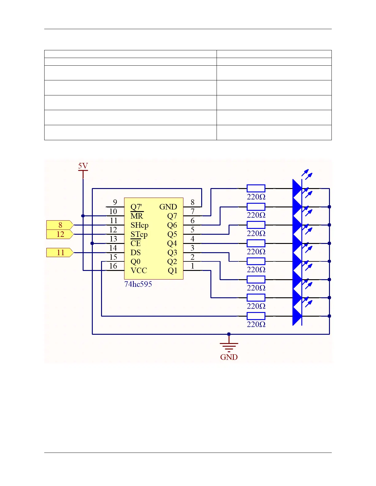
74HC595
Schematic
• When MR (pin10) is high level and OE (pin13) is low level, data is input in the rising edge of SHcp and goes to
the memory register through the rising edge of SHcp.
• If the two clocks are connected together, the shift register is always one pulse earlier than the memory register.
• There is a serial shift input pin (Ds), a serial output pin (Q) and an asynchronous reset button (low level) in the
memory register.
• The memory register outputs a Bus with a parallel 8-bit and in three states.
• When OE is enabled (low level), the data in memory register is output to the bus(Q0 ~ Q7).
160 Chapter 4. Basic Projects