User Manual 2 LCD Operation
13
Parameter Description Default Range
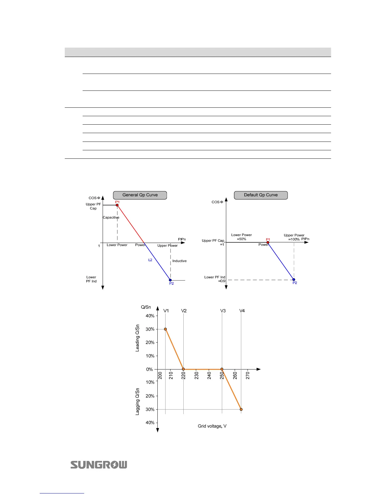
Lower PF Ind
Power factor of point P2 in the
Qp mode curve
0.900 0.9…1
Upper Power*
Output power of point P2 in
the Qp mode curve (in %)
100.0% 50%...100%
Lower Power*
Output power of point P1 in
the Qp mode curve (in %)
050.0% 0%...50%
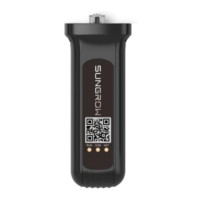
Qu
Up U Limit Grid voltage reference value 4 265.0 V 244 V...265 V
Low U Limit Grid voltage reference value 1 207.0 V -
U1 Limit Grid voltage reference value 2 220.0 V 216 V... 230 V
U2 Limit Grid voltage reference value 3 250.0 V 235 V... 255 V
Upper Q/Sn Q/Sn value of voltage V1 30.0% 0%...60%
Lower Q/Sn Q/Sn value of voltage V4 30.0% 0%...60%
*Lower Power <Upper Power
“
+”: the current leads the voltage, ”-”: the current lags the voltage”
Fig. 2-3 Reactive Power Regulation Curve in Q(p) Mode
Fig. 2-4 Reactive Power Regulation Curve in Q(U) Mode