10
Symbol Explanation
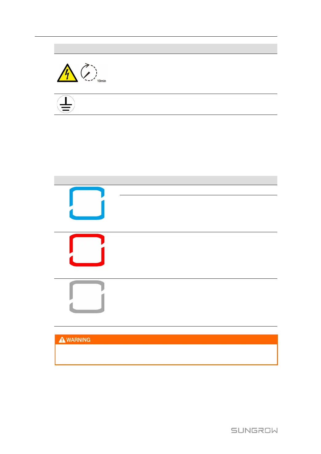
Danger to life due to high voltages!
Do not touch live parts for 10 minutes after disconnection from
the power sources.
Only qualified personnel can open and maintain the inverter.
Additional grounding point.
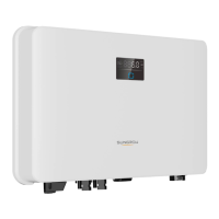
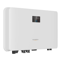
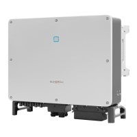
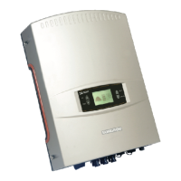
* The table shown here is for reference only. The actual product received may differ.
2.4 LED Indicator
The LED indicator on the front of the inverter indicates the working state of the inverter.
table 2-1 State description of the LED indicator
LED color State Definition
Blue
On
The inverter is operating normally.
Flashing
The inverter is at standby or startup state (not
feeding power into the grid).
Red
On
A system fault has occured.
Gray
Off
Both the AC and DC sides are powered down.
Voltage may still be present in AC side circuits after the indicator is off. Pay atten-
tion to the electricity safety during operating.
2.5 Circuit Diagram
The following figure shows the main circuit of the inverter.
2 Product Description User Manual