11
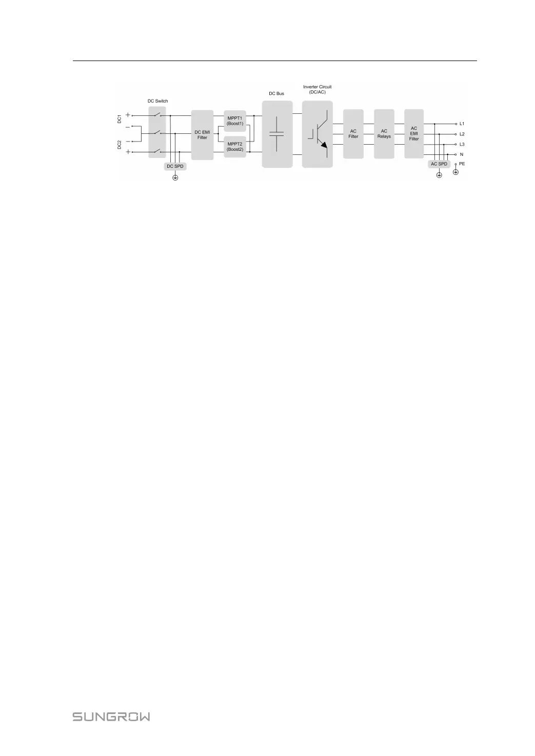
figure 2-4 Circuit Diagram (SG5.0RT for example)
• DC switches can safely disconnect the PV input when necessary to ensure the safe op-
eration of the inverter and the safety of personnel.
• The DC SPD provides a discharge circuit for the DC side over-voltage power to prevent
it from damaging the internal circuits of the inverter.
• EMI filters can filter out the electromagnetic interference inside the inverter to ensure that
the inverter meets the requirements of electromagnetic compatibility standards.
• The MPPT is utilized for DC input to ensure the maximum power from the PV array at dif-
ferent PV input conditions.
• The inverter circuit converts the DC power into grid-compliant AC power and feeds it into
the grid.
• The AC filter filters the output AC component of high frequency to ensure that the output
current meets the grid requirements.
• The AC relay isolates the AC output of the inverter from the grid, making the inverter safe
from the grid in case of inverter failure or grid failure.
• The AC SPD provides a discharge circuit for the AC side over-voltage power to prevent it
from damaging the internal circuits of the inverter.
2.6 Function Description
Basic Function
• Conversion function
The inverter converts the DC power from the PV array to the AC power, in conformity with
the grid requirements.
• Data storage
The inverter logs running information, error records, etc.
• Parameter configuration
The inverter provides various parameter configurations for optimal operation. Parame-
ters can be set via the iSolarCloud App or the cloud server.
• Communication interface
User Manual 2 Product Description