27
table 5-1 Terminal Description
No. Name
Description
Decisive Volt-
age
Classification
1
PV1+, PV1–, PV2+,
PV2–, PV3+, PV3–,
PV4+, PV4–
MC4 terminals for PV input.
The terminal number depends on in-
verter model.
DVC-C
2 COM1
Communication accessory port to be
connected to WiNet-S for countries
except Brazil or to WiFi for Brazil.
DVC-A
3 AC
AC terminal to connect to the grid.
DVC-C
4
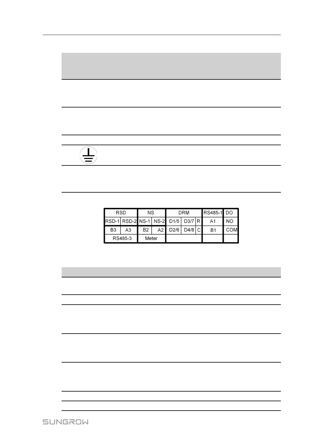
External grounding terminal. Not applicable
5 COM2
Communication connection for DI/
DRM, DO, Logger and smart energy
meter.
DVC-A
The pin definition of COM2 terminal is shown in the following label.
figure 5-2 Label of COM2 Terminal
table 5-2 Label Description of COM2 Terminal
Label
Description
RSD
RSD-1,
RSD-2
Reserved
NS
NS-1, NS-2
For inverter emergency stop
DRM
D1/5, D2/6,
D3/7, D4/8,
R, C
For external Demand Response Enabling Device ("AU"/
"NZ")
For Ripple Control
RS485-1
A1, B1
For inverter daisy chain
(Cannot be used simultaneously with COM1 port for WiNet-
S)
DO
NO, COM
External alarm interface, e.g. light indicator and/or buzzer
The external DC voltage should not be higher than 30 V and
the current not higher than 1 A.
RS485-3
A3, B3
Reserved
Meter
A2, B2
Smart energy meter interface
User Manual 5 Electrical Connection