사절장치의 조정 그림13-2. ( 17.2)
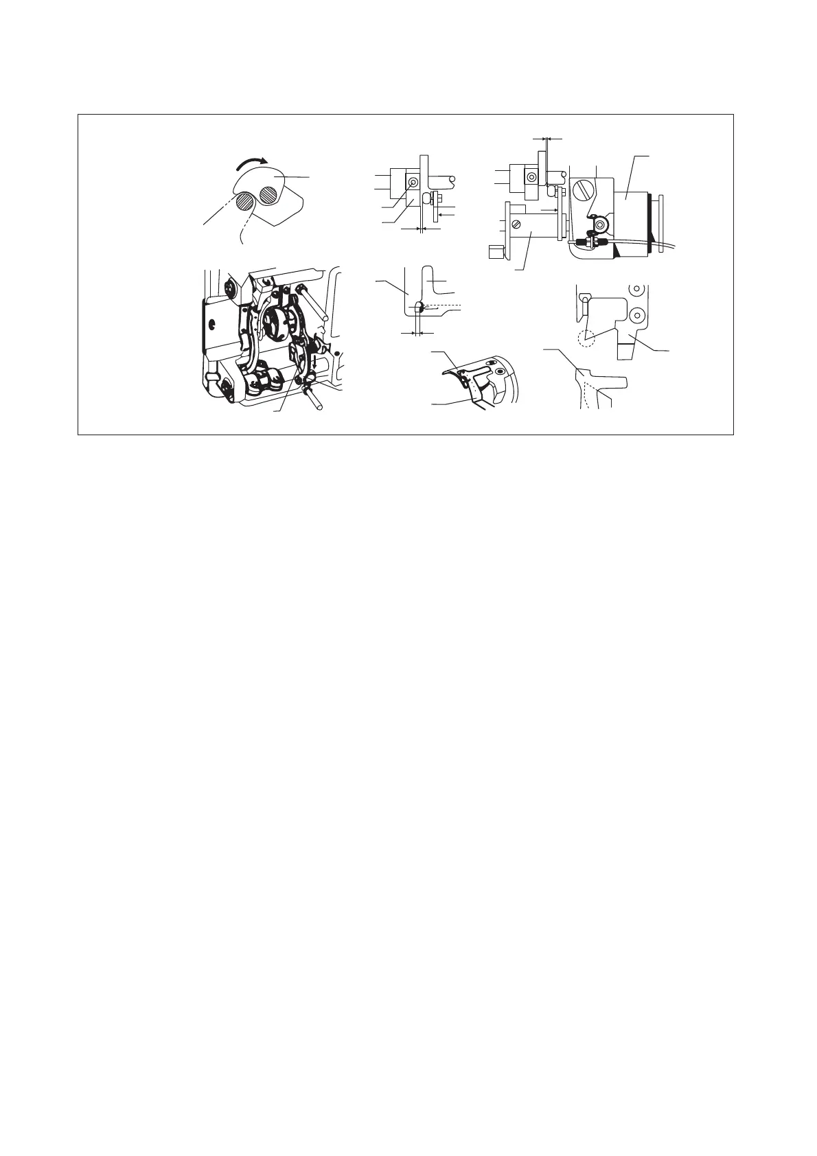
ADJUSTING THE THREAD TRIMMING EQUIPMENT (Fig.17.2)(ROUND KNIFE)
사절 캠의 위치 조정1.
기계의 핸드 휠을 돌려 바늘대가 최하 위치에서 올라온 위치일 때 사절 솔레노이드 를5mm ④
눌러 롤러가 사절 캠 의 오목한 부분에 닿도록 합니다 그런 다음 고정나사 를 사용하여.①②
위치를 고정합니다 사절 솔레노이드 를 원위치 시켰을 때 사절 캠과 사절 구동축 끝단 간격이.④
가 되도록 나사 를 풀어 사절 캠 을 조정하십시오0.5mm .②①
고정나사 를 의 힘으로 조여 주십시오( 40Kgf Cm .)② ․
동 고정 메스의 위치 조정2. /
사절 구동축 앞부분이 캠을 지나쳐 동메스 의 끝단이 고정메스 앞부분과 0.2~0.5mm③⑦⑧
겹치도록 합니다 동 고정메스가 겹치지 않으면 사절 구동축이 캠 을 지나치기 전에 동메스의./ ①
끝단이 고정메스 앞부분과 겹치도록 메스축 로드 를 움직여 조정하고 나사 를 조여 주십시오.⑥⑤
1. Adjusting the position of the thread trimming cam.
If you run the hand wheel of the machine, the needle bar goes from the bottom upto
5mm, then the thread trimming solenoid is pressed to impel the roller ball touches to④
the concave of the thread trimming cam , Then use the position screw to tighten it①②
in casual. And then replace the thread trimming solenoid , while loose the screw to④②
adjust the cam , the clearance of the end plane between the cam and thread trimming①
driving shaft is 0.5mm.(Use the torsion with 40Kgf·cm to tighten the position screw )②
2. Adjusting the position of the counter knife and moving knife.
When the head of the thread trimming driving shaft exceeds the cam, the mesh③
between the front place of the counter knife and the edge of the moving knife⑧⑦
is 0.2-0.5mm. If they are not meshed, moves the knife shaft crack rod before the⑥
thread trimming driving shaft exceeded the cam , the front plane of the counter①
knife and the edge of the moving knife is meshed, then tighten the screw⑧ ⑤
-20-
Fig.17.2
Rotary direction
Trimming
0.6-0.8mm
High speeding
0.5mm
0.2-0.5mm
①
①
②
③
③
⑤
⑥
⑦
⑦
⑦
⑧
⑧
⑧
④
 Loading...