23
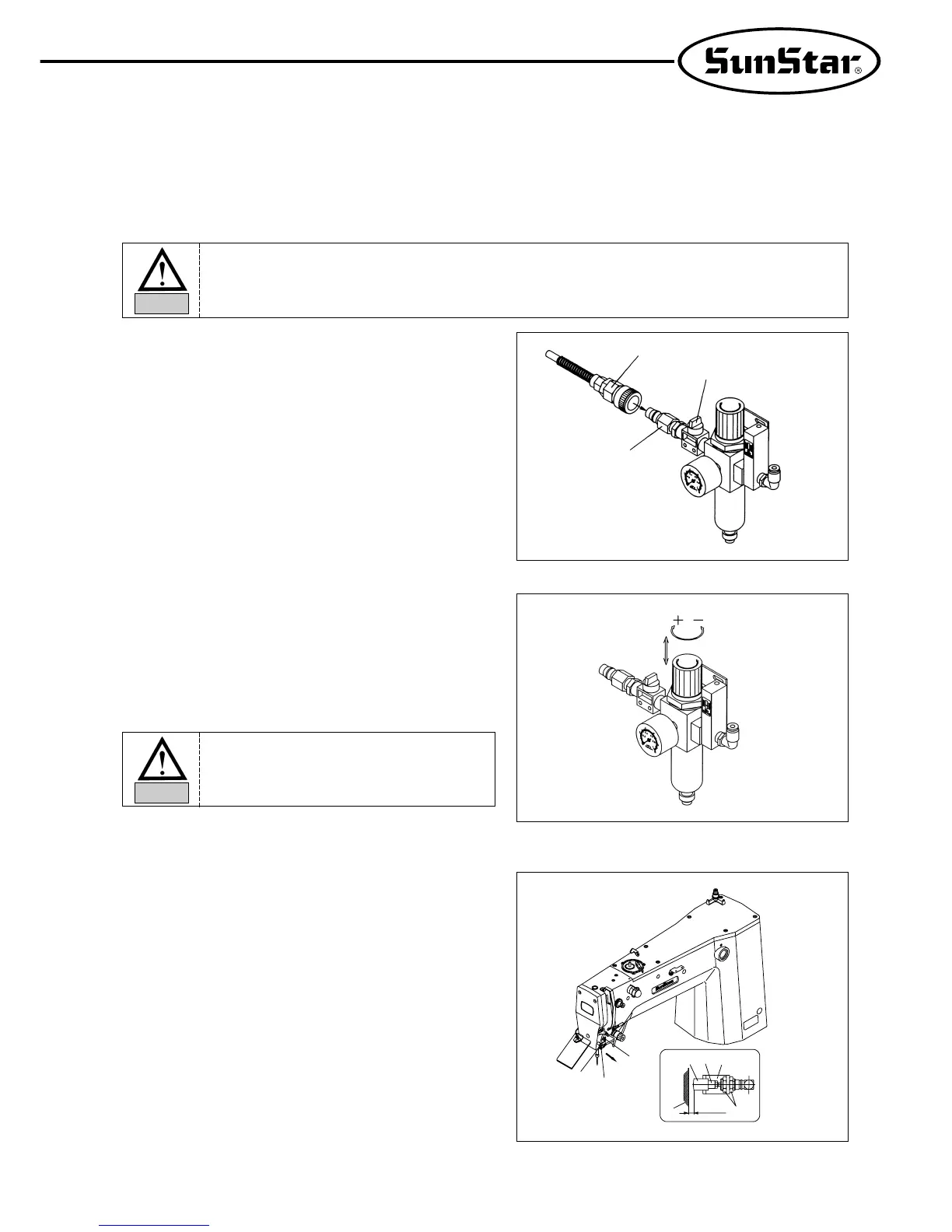
[ Fig. 30 ]
A. Please connect quick joint socket ① that pressed air was
connected to the quick joint plug ② attached to the table.
B. Open the finger valve ③ and input the pressed air.
[ Reference ]
If you close the finger valve after you use it, automatically
dischange the remained air and the remained pressure is
indicated as 0 MPa (0 kgf/cm²)
11) Compressed Air Input Air Pressure Adjusting Method
[ Fig. 31 ]
C. After pulling the adjusting handle located on th upper part
of filter regulator as shown in the right figure, if you turn it to
clockwise direction, the pressure rise and if you turn it to
counter clockwise direction, the pressure drops. Therefore,
after adjusting to the proper pressure 0.49∼0.54MPa
(5∼5.5kgf/cm²) indicated on the pressure gauge, press
the adjusting handle to the original location and fix it.
[ Fig. 32 ]
A. Please confirm if upper thread holder pin cylinder knuckle
① and cap ② are located in the center of upper thread
passage.
B. If they are not located in the center, unfasten two pieces
of joint screw ④ of upper thread holder pin cylinder
bracket ③ and adjust to be located in the center. Then
unfasten two joint screw ④ and adjust to be located in
the center and fasten joint screw ④ tightly.
C. Standard distance between end of knuckle cap ② and
ARM ⑤ should be 4mm.
D. In order to adjust this, unfasten two pin cylinder nut ⑥
and adjust distance of front and back.
Then if adjustment is finished, fasten two nut ⑥ tightly.
12)
Adjusting Method of Upper Thread Holding Device (Option)
①
⑥
③
②
⑤
④
⑥
③
③
②
①
4mm
Please Operate under power-off status for prevention of safety assiden.
Note
If the air pressure drops while using is (less
than 4kgf/cm²), it shall be indicated as
“error”and operation of the machine shall
stop. [Er07]
Note

 Loading...