34
[ Fig. 57 ]
B. After adjusting to correct the distance from the presser
foot drive cam to the thread winder drive wheel to be
1mm, fasten the joint screw.
[ Fig. 58 ]
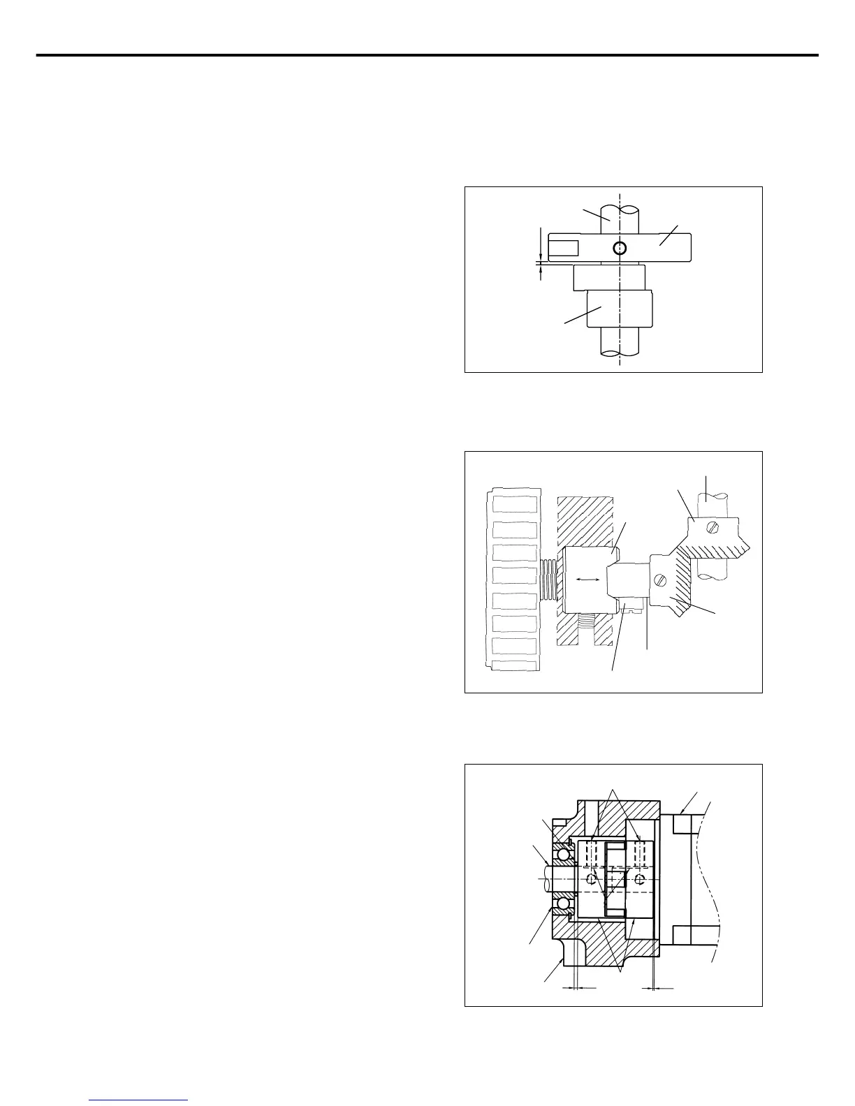
[ Fig. 59 ]
A. When you mount the coupling on the servo motor, fit the
screw No. 1 of coupling to the flat surface of the servo
motor shaft and make the clearance between the
coupling and servo motor 0.7mm.
B. When you mount the coupling on the upper shaft, fit the
screw No. 1 of coupling to the flat surface of the upper
shaft and make the clearance between the coupling and
upper shaft bushing(R) 2mm.
C. After mounting both couplings, check the positions of
each screws to the aligned.
※ If the positions of each screws are not aligned, the needle
does not stop normal position.
14) Mounting the Direct Motor and Adjusting Method
Upper Shaft front
Boothing
Thread Winder
Drive Wheel
Upper Shaft
Roller
Hand Pulley Shaft
Hand Pulley
Bushing
Upper Shaft
A. Tighten the screw after putting the hand pulley gear
and the hand pulley shaft tip in accord.
B. Adjust the clearance of hand pulley gears and and
tighten the screws.
C. Move the bushing in the direction of the arrow to reduce
the backlash between gears and when the roller is
on the end of the pulley bushing.
13) Adjusting the Hand Pulley Device
O-Ring
Screw No.1
Servo Motor
Upper Shaft
Upper Shaft Rear
Bushing
Coupling
Cutting Position
ARM
2
0.7
1mm

 Loading...