28
[ Fig. 43 ]
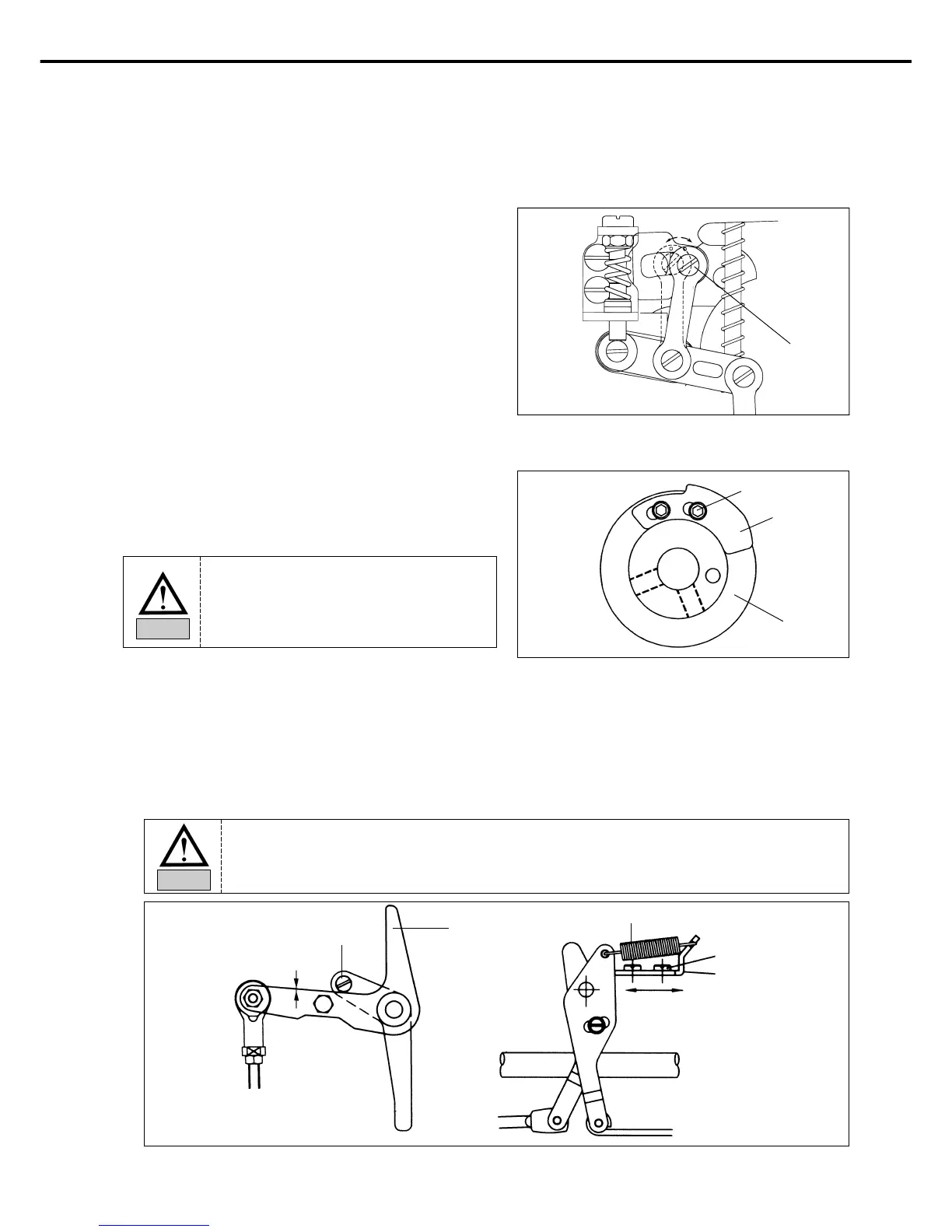
D. Adjustment of Presser Foot Stoke(Adjustment of Presser
Foot UP/DOWN Motion)
After unfastening stud screw ① of presser foot adjusting
arm, placing it to A direction, presser foot stroke
increases. Placing to direction B, stroke decreases. (It is
set to 4mm at the moment of factory shipping).
①
B
A
[ Fig. 44 ]
A. How to Set the Thread Release Notch
Place the notch so that the right side of the slot of the
thread release notch ① touches circumference of the
notch screw ②, and then fix with a screw.
8) Adjusting the Parts for Thread Release
②
①
Thread
Trimming
Cam
B. How to Set the Thread Release Stopper
ⓐ Remove the thread release return spring.
ⓑ After unfastening the thread release stopper screw, adjust the trimming drive link and the thread release lever
pin 0.3mm apart from each other. Then, attach the arm to the thread delay stopper completely.
When the thread release stopper is pushed to the right, the space between the trimming drive link and the
thread release lever pin is reduced. And it is enlarged when the stopper is pushed to the left.
ⓒ Hang on the thread releasd return spring.
[ Fig. 45 ]
Thread Release
Lever Pin
Thread Triming
Driving Link
Screw
Thread Rlelease
Stopper
Return Spring
Widen Narrow
0.3mm
The remaining amount of thread may
not be enough or not be regular and
the thread may be unfasten from the
needle if the notch is not set in the
right position.
Caution
Use a tool when removing or attaching the thread delay spring to prevent accidents.
Caution

 Loading...