2-20
X10SBA/X10SBA-L User’s Manual
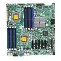
X10SBA(-L)
Rev.
1.01A
JSMB1
J31
JBT1
BT2
M-SATA0M-SATA1
M-SATA2
M-SATA3
JP1
LAN1LAN2
JDIMM2
PJ1
JF1
JTPM1
JOH1
JSPDIF_OUT
JPUSB1
JPAC1
JPME2
JD1
VGA
FAN1
FAN2
I-SATA1
COM4
COM2
SP1
JSD1
JDIMM1
LED3
LED4
LED2
JPW1
SMBUS1
SLOT1 PCI-E 2.0 X2 (IN X8)
USB4/5
USB6
AUDIO FP
SODIMM2 (1.35V only)
USB1(2.0)
USB0(3.0)
CPU
(Install first)SODIMM1(1.35V only)
eDP
Non-ECC DDR3 Required
HDMI/DP
COM3
FP CTRL
BIOS
BAR CODE
J1
(for mini-PCI-E only)
(for M-SATA only)
J2
COM1
(for X10SBA only)
(for X10SBA only)
(for X10SBA only)
(for X10SBA)
LED1
LED5
USB2/3
I-SATA0
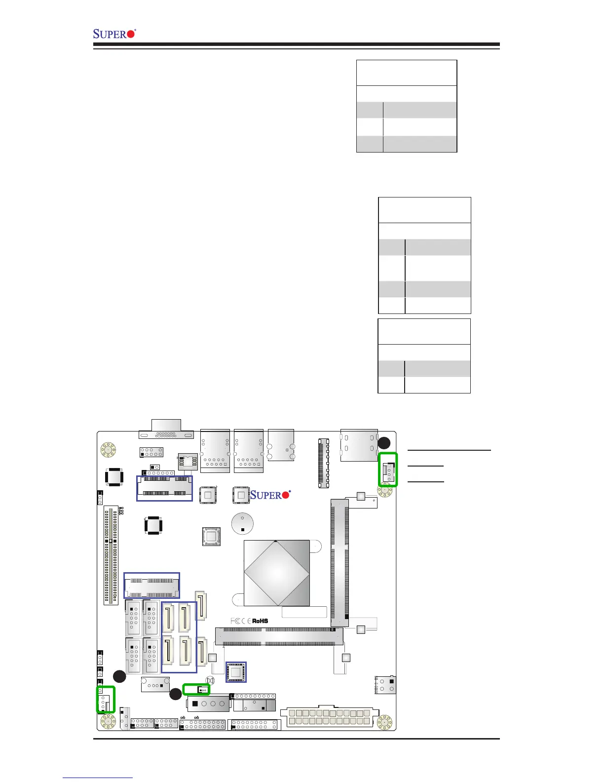
Fan Header
Pin Denitions
Pin# Denition
1 Ground (Black)
2 2.5A/+12V
(Red)
3 Tachometer
4 PWM_Control
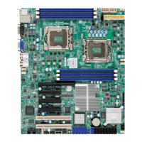
Fan Headers (Fan 1/Fan 2)
The X10SBA(-L) has two fan headers (Fan 1/
Fan 2). These fans are 4-pin fan headers. Al-
though pins 1-3 of the fan headers are backward
compatible with the traditional 3-pin fans, we
recommend the use 4-pin fans to take advan-
tage of the fan speed control. This allows the
fan speeds to be automatically adjusted based
on the motherboard temperature. Refer to the
table on the right for pin denitions.
A
B
B. SATA DOM PWR
B. Fan 1
C. Fan 2
C
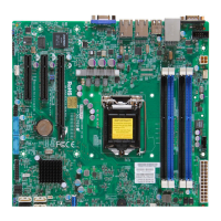
Chassis Intrusion
Pin Denitions (JL1)
Pin# Denition
1 Intrusion Input
2 Ground
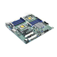
DOM PWR Connector (JSD1)
The SATA Disk-On-Module (DOM) power con-
nector, located at JSD1, provides power to a
solid state DOM storage device connected to
one of the SATA ports. See the table on the
right for pin denitions.
DOM PWR
Pin Denitions
Pin# Denition
1 5V
2 Ground
3 Ground