2-26
X10SBA/X10SBA-L User’s Manual
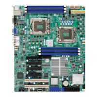
2-7 Jumper Settings
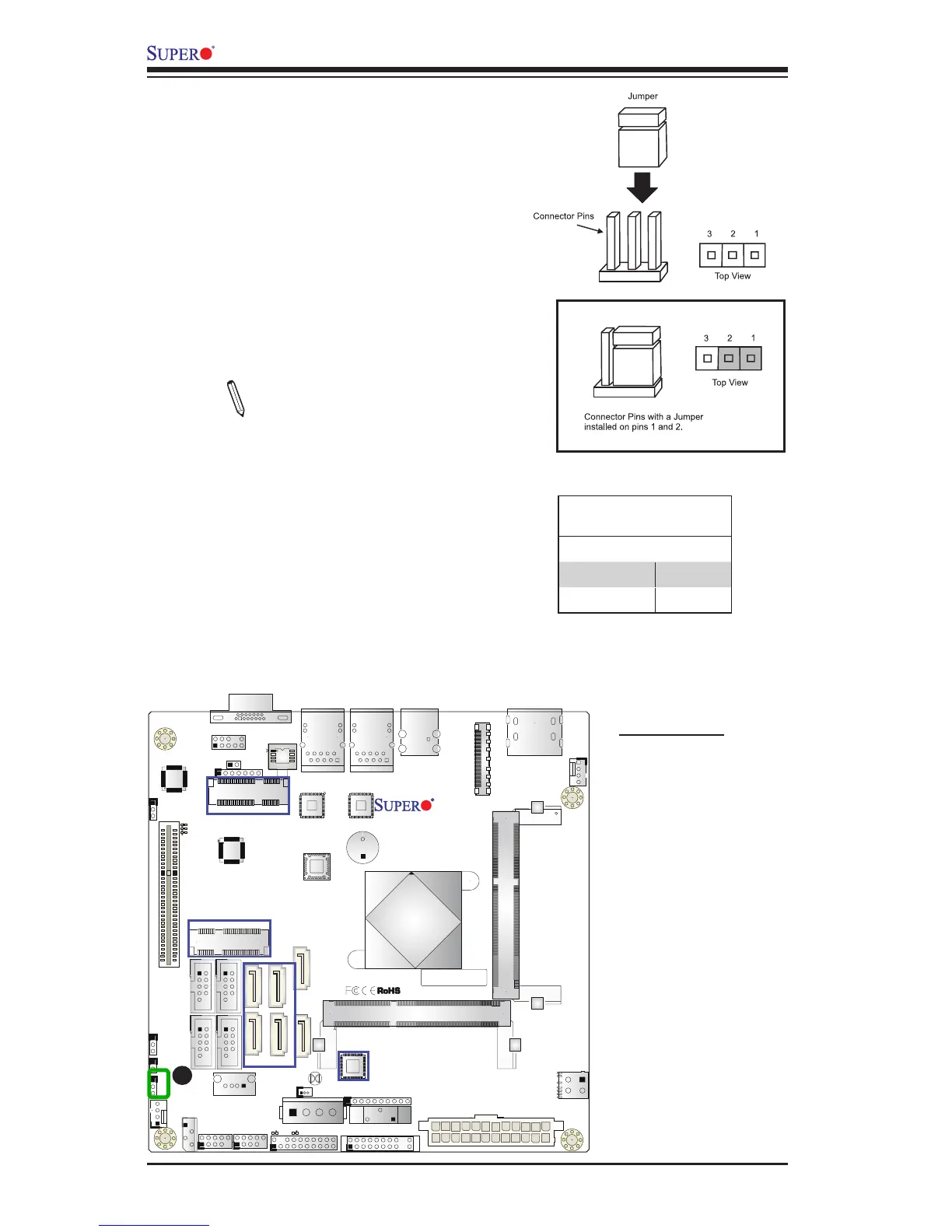
Explanation of Jumpers
To modify the operation of the mother-
board, jumpers can be used to choose
between optional settings. Jumpers create
shorts between two pins to change the
function of the connector. Pin 1 is identied
with a square solder pad on the printed
circuit board.
Note: On-two pin jumpers,
"Closed" means the jumper is on,
and "Open" means the jumper is
off the pins.
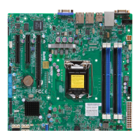
A. Audio Enable
X10SBA(-L)
Rev.
1.01A
JSMB1
J31
JBT1
BT2
M-SATA0M-SATA1
M-SATA2
M-SATA3
JP1
LAN1LAN2
JDIMM2
PJ1
JF1
JTPM1
JOH1
JSPDIF_OUT
JPUSB1
JPAC1
JD1
VGA
FA N1
FAN2
I-SATA1
COM4
COM2
SP1
JSD1
JDIMM1
LED3
LED4
LED2
JPW1
SMBUS1
SLOT1 PCI-E 2.0 X2 (IN X8)
USB4/5
USB6
AUDIO FP
SODIMM2 (1.35V only)
USB1(2.0)
USB0(3.0)
CPU
(Install first)SODIMM1(1.35V only)
eDP
Non-ECC DDR3 Required
HDMI/DP
COM3
FP CTRL
BIOS
BAR CODE
J1
(for mini-PCI-E only)
(for M-SATA only)
J2
COM1
(for X10SBA only)
(for X10SBA only)
(for X10SBA only)
(for X10SBA)
LED1
LED5
USB2/3
I-SATA0
Audio Enable/Disable
Jumper Settings
Both Jumpers Denition
Pins 1-2 Enabled
Pins 2-3 Disabled
Audio Enable (JPAC1)
JPAC1 allows you to enable or disable the
onboard audio support. The default position
is on pins 1 and 2 to enable onboard audio
connections. See the table on the right for
jumper settings.
A