Chapter 2: Installation
2-31
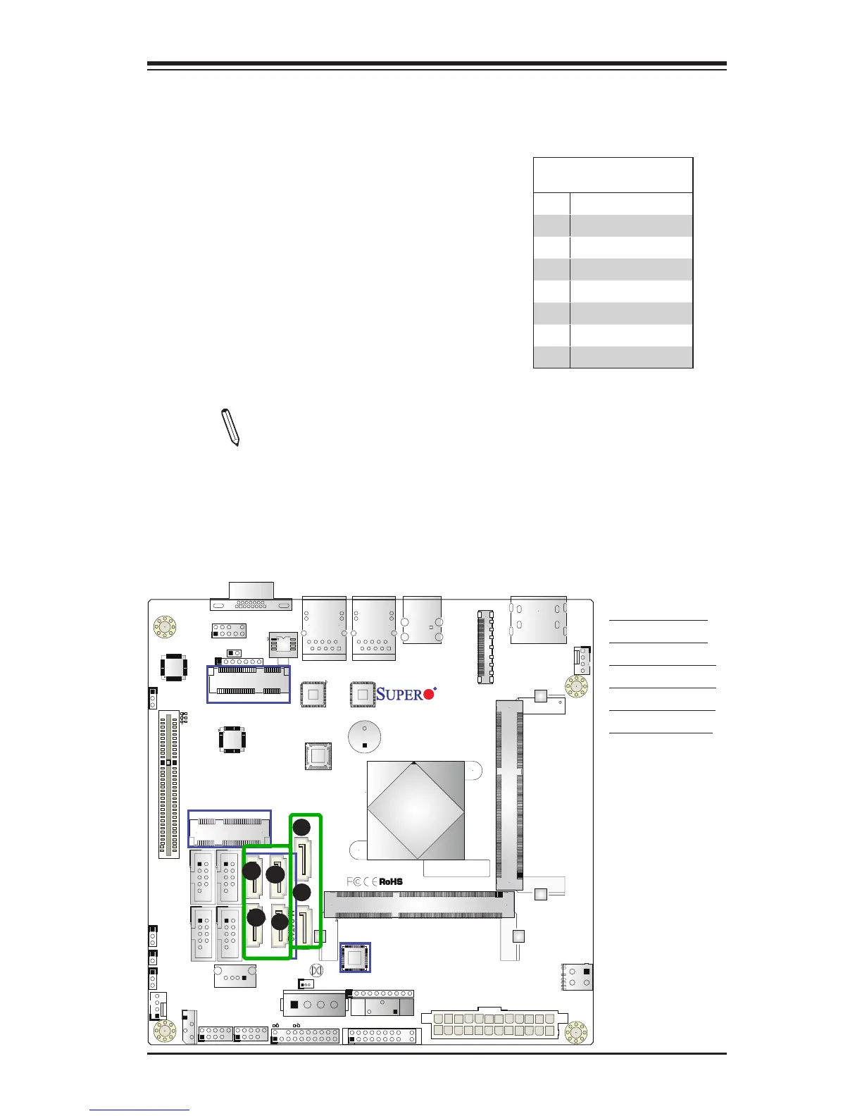
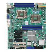
X10SBA(-L)
Rev.
1.01A
JSMB1
J31
JBT1
BT2
M-SATA0M-SATA1
M-SATA2
M-SATA3
JP1
LAN1LAN2
JDIMM2
PJ1
JF1
JTPM1
JOH1
JSPDIF_OUT
JPUSB1
JPAC1
JPME2
JD1
VGA
FAN1
FAN2
I-SATA1
COM4
COM2
SP1
JSD1
JDIMM1
LED3
LED4
LED2
JPW1
SMBUS1
SLOT1 PCI-E 2.0 X2 (IN X8)
USB4/5
USB6
AUDIO FP
SODIMM2 (1.35V only)
USB1(2.0)
USB0(3.0)
CPU
(Install first)SODIMM1(1.35V only)
eDP
Non-ECC DDR3 Required
HDMI/DP
COM3
FP CTRL
BIOS
BAR CODE
J1
(for mini-PCI-E only)
(for M-SATA only)
J2
COM1
(for X10SBA only)
(for X10SBA only)
(for X10SBA only)
(for X10SBA)
LED1
LED5
USB2/3
I-SATA0
2-9 SATA Connections
SATA 2.0 & SATA 3.0 Connections
Two Serial ATA (SATA) 2.0 connectors (I-
SATA 0/1) are located on the motherboard to
provide optional power source. In addition,
four SATA 3.0 ports (M-SATA 0-3) are located
on the X10SBA. Please note that SATA 3.0
ports are not available on the X10SBA-L.
Serial Link connections provide faster data
transmission than legacy Parallel ATA. See
the table on the right for pin denitions.
SATA 2.0/3.0 Connectors
Pin Denitions
Pin# Signal
1 Ground
2 SATA_TXP
3 SATA_TXN
4 Ground
5 SATA_RXN
6 SATA_RXP
7 Ground
A. I-SATA 2.0 #0
B. I-SATA 2.0 #1
C. M-SATA 3.0 #0
D. M-SATA 3.0 #1
E. M-SATA 3.0 #2
F. M-SATA 3.0 #3
A
B
C
D
E
•Note 1: M-SATA 0-3 are not available on the X10SBA-L.
•Note 2: I-SATA1 support is available only when the
mSATA MUX slot @ J2 is not in use. J2 and I-SATA1
cannot be used together.
DF