knob will come on when INTELLISAND is
operating. (Fig. 11 a) When the load is decreased,
INTELLISAND will automatically increase the feed
rate to the pre-selected speed. INTELLISAND does
not engage when brush sanding or if drum sanding at
a slower RPM than recommended.
S B D C/C
When a nylon or wire brush is worn and needs
changing, the bristles will either have fractured and
the brush head looks “bald” or the bristle length
has worn and the bristles are too short for e ective
brushing.
When an abrasive or cloth brush is worn, the brushing
material will become smooth or the brush will be
considerably smaller in diameter as compared to new.
Please call SuperMax Tools if you have any questions.
Brush life can vary considerably, due to RPM, contact,
type of brush, and material being brushed.
Some types of brush heads, some adder brushes, for
example, will allow changing of the brush material by
the operator.
When using a wire brush for “distressing” wood,
slowing brush RPM, using light contact and a
moderate feed rate generally will give the best nish
and longest brush life. When using a wire brush on
metal, it is important to use a light contact of the
bristle tips. Nylon Brushes. If a nylon brush brush
becomes uneven dressing the tips of bristle brush to
maintain uniform brush wear will be a bene t.
Dressing Instructions:
Staple or glue a wide sheet of 60 grit sandpaper to
a 1/2” thick at wood surface. Strips of narrow
sandpaper can also be used. Lower the brush so the
tips of the bristles contact the sandpaper by 1/32”. Set
the conveyor speed to approximately 50% feed rate.
Pass the abrasive loaded board through the machine
until the brush bers are sharp and even
S D D C
Determining the depth of cut is the most
IMPORTANT set-up procedure before operating as
a drum sander. It may take some experimentation to
determine the proper depth of cut, given the variables
of abrasive grit, type of wood, and conveyor feed rate.
Practicing on scrap before sanding a project can be
bene cial.
A good rule-of-thumb when sanding is to place the
workpiece under the drum and lower the sanding
head until the workpiece contacts the drum but the
drum can still be rotated by hand. When making
successive passes, lower the sanding head no more
than the thickness of the grit abrasive, I.e. 1/8-1/16
of a turn for 80 grit and less for ner grits. Note: one
revolution of the height adjustment handle moves the
sanding head 1/16”.
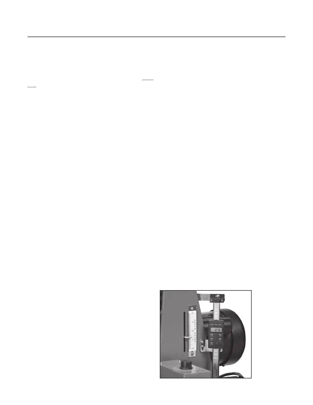
D G O
e depth gauge (see Fig. 5) measures the distance
between the conveyor table and the bottom of the
sanding brush or drum. e sanding head must
be parallel to the conveyor bed surface. To calibrate
the depth gauge, loosen the two screws holding the
scale. Lower the brush or sanding head (with abrasive
installed) until the head touches the conveyor belt.
Slide the scale to align with the pointer at the “0”
mark. Tighten the two screws holding the scale. An
optional DRO (digital read out) for depth is available.
Fig. 12. is o ers the most precise reading of sanded
thickness and allows for accurate repeatability of a
thickness. Great when making parts that must be an
exact thickness or when matching a thickness.
To operate, turn ON and select standard inch “in” or
metric millimeter “mm”. Lower drum, with abrasive
installed, until it touches the conveyor belt. Press
“zero” button to calibrate.
O Y SB
Fig. 12 Depth Gauge and optional DRO