Installing Heads
Installing Heads
Supermax Drum Sanders © 2018 Laguna Tools 7/31/2018
EN
Installing Heads
WARNING! Unplug machine from power prior to proceeding!
NOTICE! Make sure to follow instructions about set screws and cotter pins. Failures to remove a set screw or
cotter pin can damage the machine.
NOTICE! USE EXTREME CAUTION TO NOT DROP THE ALUMINUM DRUM OR BRUSH HEAD DURING THIS
PROCESS. Allays place in secure location when not installed.
NOTICE! Never store brush heads on the brushing, stand the brush-head up in a vertical positions to prevent flat
spots.
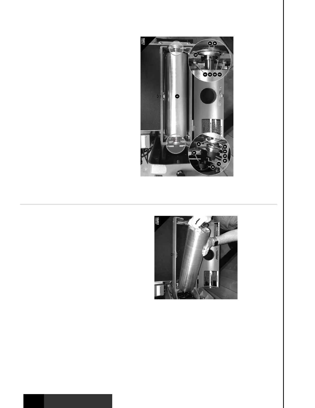
Fig SM01: Drum Head Assembly Installation/Removal. (1) Drum Head. (2) Mounting
Bolts/Nuts. (3) Bearing to Shaft Set Screws. (4) Bearing Seat. (5) Bearing. (6) Coupling.
(7) Spider.
The drum can be interchanged between the different heads offered for the 19|38
combination machine. Although a cumbersome process to the uninformed, the
drums interchange easily by removing the bolts and seating the spider coupling
properly. Please take the time to learn these instructions prior to attempting a head
change.
NOTICE! Pay particular attention to the set screws and the removed drum or head.
Make sure to release set screws prior to removal and to tighten them only when
instructed to. Make sure to place the removed drum head in a location where it can
not fall - it will loose a fight against a concrete floor every time.
NOTICE! This help section is only intended for the 19|38 combination drum/brush
sanding machine (SKU: SUPMX-71938). The standard 19|38 (SKU: SUPMX-71938-
D) is only compatible with the sanding drum head included with purchase.
Removing (Head)
Tools Needed: Size 14MM Wrench. Allen Wrenches
1. Make sure Sander is disconnected form power and cannot be turned on.
2. Use 14mm wrench to remove the four (2) mounting bolts/nuts from the left and
right side. SEE STEP 3 PRIOR TO REMOVAL.
3. Remove all four (3) Bearing to Shaft Set Screws with an allen wrench. The four
(4) Bearing seats should now be loose enough to remove the drum head.
4. Remove the (1) Drum head assembly by tilting the drum head upright from the
left side. Pull the drum head away carefully not to bump metal parts.
Installing (Head)
Tools Needed: Size 14MM Wrench. Allen Wrenches. WD40 or other Lubricant
1. Make sure machine is disconnected
from power and cannot be turned on.
2. Check the (6) coupling that is
connected to the motor shaft. The motor
shaft should be flush with the inner face
of the coupling. If not, adjust it by
loosening the (not shown) two set screws
on the coupling, position it flush, and
tighten the set screws back in place.
3. Check the (6) coupling that is
connected to the drum/brush shaft. The
drum/brush shaft should be flush with
the inner face of the coupling. If not,
adjust it by loosening the (not shown)
two set screws on the coupling, position it
flush, and tighten the set screws back in
place.
4. Remove all four (3) Bearing to Shaft Set Screws with an allen wrench. DO NOT
remove the set screws on the coupling unless they need to be adjusted
(preceding steps). This will allow the bearings to move left to right on the shaft,
giving clearance to position the (6) couplings and (7) rubber spider together.
5. IMPORTANT. Place one if the (4) bearing seats behind the motor shaft coupling
and motor shaft as shown in figure SM01. Make sure each bearing seat is
installed after each bearing on the shaft.
6. Reference the top right of figure SM01. Place the (7) spider in the drum/brush
coupling.
7. With the couplings position as shown in figure SM01, install the drum head by
tilting the left side and aligning the couplings such that the brush/drum
couplings sits inside the motor shaft coupling. NOTICE: WD40 can prevent
damage to the rubber spider and make the installation easier.
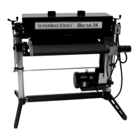
8. Use moderate force as shown in figure SM02 to seat the coupling s together.
Lower the (1) drum head into the left casting slot.
9. Now that the spider coupling is in place, set the position by fastening the four
(2) mounting bolts/nuts with a 14mm wrench. The order is: bolt, bearing seat,
bearing, bearing seat, cast iron, nut - as shown in figure SM01. NOTICE: Make
sure the four (3) bearing to shaft set screws are removed while fastening the
four (2) mounting bolts/nuts. The mounting bolts will position the shaft
correctly as long as steps 1 and 2 were performed.
10. Tighten down the four (3) bearing to shaft set screws.