A T SB S
U Y SB
Your 19-38 Combo sander has been shipped mostly
assembled from the factory. If any damage has
occurred as a result of shipment, notify the
transportation company as soon as possible and
ask them to make an immediate inspection. Ask
for a damage or loss report. Also notify your
dealer of any loss or damage during shipment. See
enclosed Warranty Statement.
Important: To avoid problems and potential damage
to the machine, please read through the unpacking
instructions below before proceeding to set up the
machine in your shop.
1. Assemble stand or prepare dedicated bench for
sander attachment
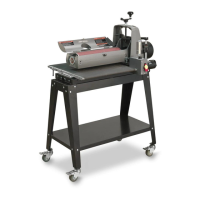
2. Open “Box 1” with main sanding unit. Remove
cardboard liner. Open plastic bag.
3. Cut each corner of Box 1 to fold sides at,
providing access to sanding unit. (Fig 2)
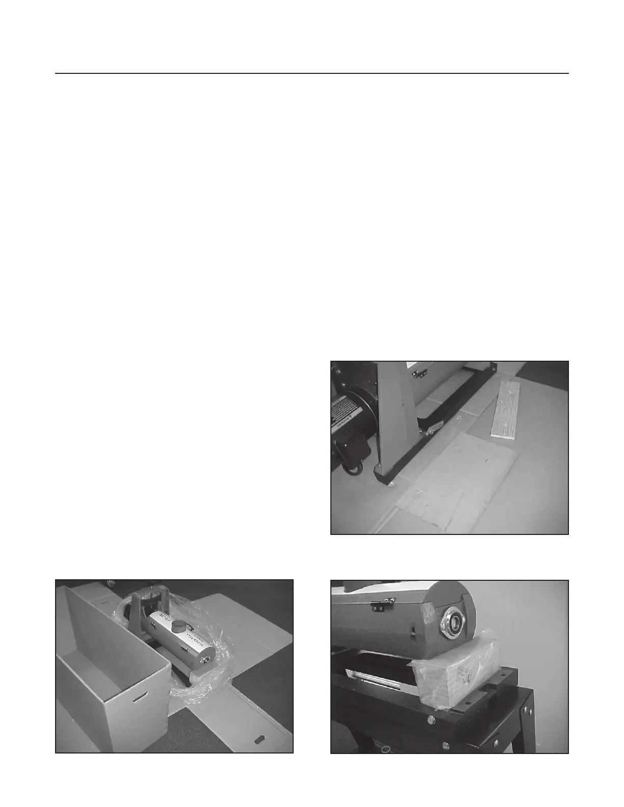
4. Remove two wood packing plates from bottom of
sanding unit. (Fig 3)
5. With one or two helpers, place sanding unit on
stand or bench and attach securely. Use bolts from
packing plates.
6. Install knob to height adjustment handle, nger
tighten nut to knob. read stud from knob
into hand wheel (Fig 2). Tighten nut against
handwheel.
7. Using handle, raise sanding head to high position
and remove packing block from under carriage
arm and motor, if so equipped. (Fig 4)
8. Remove conveyor from packaging and place on
sanding unit. e conveyor motor should be near
main motor and depth gauge.
9. Install two lock washers and two at washers on
studs on outboard side of conveyor.
10. Install lock washer and at washer onto two
socket head (or hex head bolts) and install into
ange of conveyor bed on inboard (motor side).
Keep support plate in place on inboard side and
make sure “fast lever” is positioned up. Fig. 4A
11. Tighten all bolts and nuts.
Fig. 2 Open plastic, remove liner, cut box
Fig. 4 Secure to stand, remove packing block
Fig. 3 Remove packing plates