S U Y SB
H A
e brush/drum height is controlled by the height
adjustment handle (Fig.5). Turning the handle raises or
lowers the sanding head. One revolution of the handle
raises or lowers the table 1/16 of an inch.
Before operating height adjustment, be sure the
packing-block is removed. It is located under the
outboard end of the carriage arm (Fig. 3). Raise drum/
brush to remove.
B A
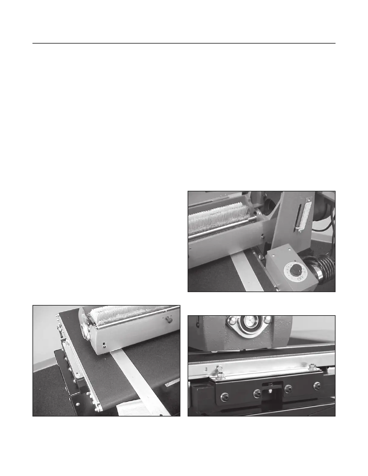
e brush must be parallel to the conveyor bed surface.
Brush alignment can be visually checked by raising the
tension rollers (Fig. 6) to their highest position (See
Tension Roller Adjustment page 9) and lowering the
head so the brush just contacts the conveyor surface.
Brush contact should be equal across the width of the
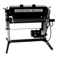
conveyor. Brush misalignment can be corrected by
loosening the four cap screws on the outboard edge of
the conveyor and turning the 7/16” adjustment nut
to bring the conveyor parallel to the brush or drum.
See Fig. 7
D A
Check alignment when using sanding drum. After
installing sanding drum, remove abrasive from drum.
Using a at piece of wood or aluminum as a thickness
gauge, insert it between the conveyor belt and the
drum on the right (inboard) side of the machine (Fig.
5). Lower the sanding head so the drum just contacts
the thickness gauge. en, holding up the front
tension roller, check both sides of the drum using the
thickness gauge. If the drum is not parallel, loosen
the four socket head cap screws (along the outboard
edge of the conveyor)and raise or lower the conveyor
with the 7/16” adjustment nut to achieve parallel
alignment. Tighten the four socket head cap screws.
Fig. 6 Checking brush alignment and table height
adjustment (outboard side).
Fig. 7 Adjusting brush alignment.
Fig. 6A Checking brush alignment (inboard side).