Chapter 5: Advanced Motherboard Setup
5-3
Figure 5-1. Front Control Panel Header Pins (JF1)
5-3 I/O Ports
See Figure 5-2 below for the descriptions of the various rear I/O ports.
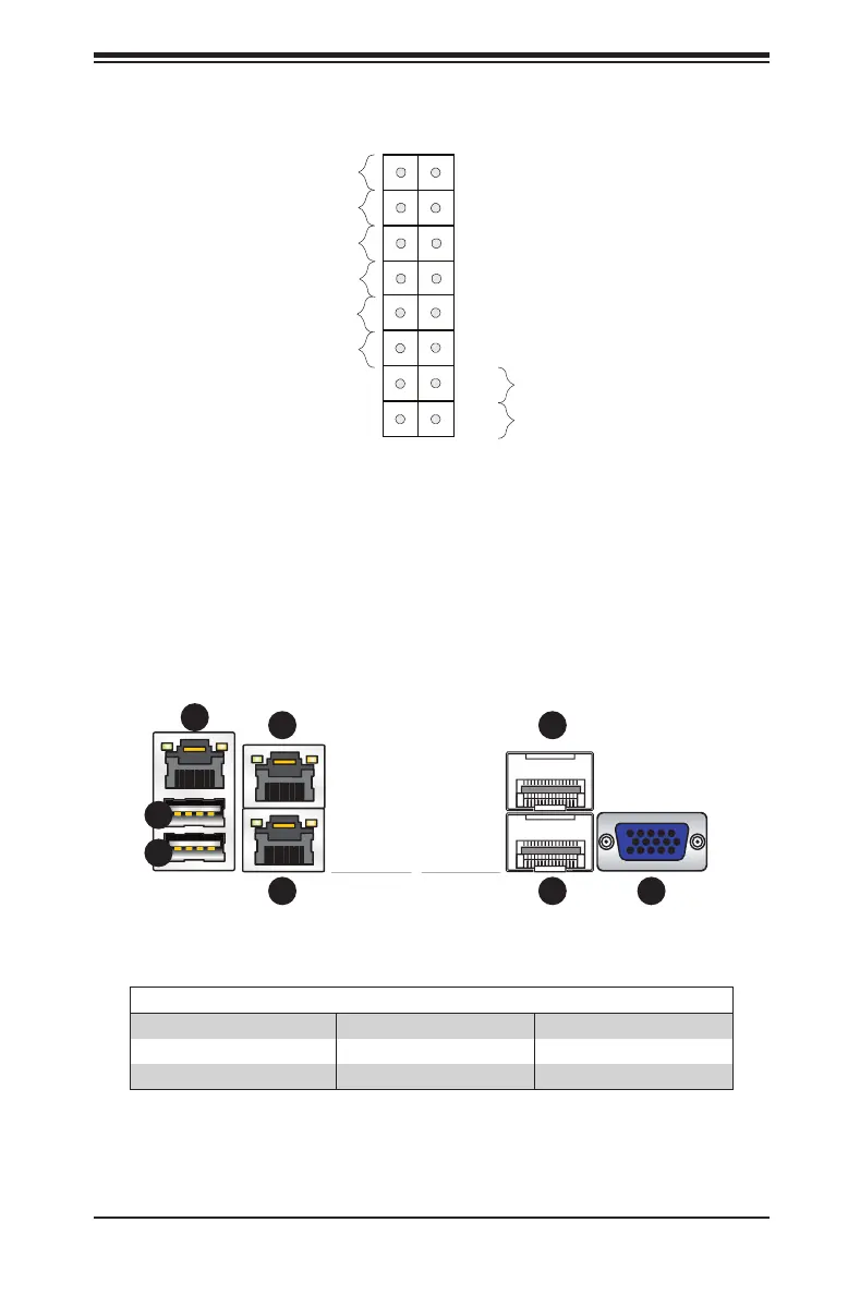
Figure 5-2. Rear I/O Ports
Rear I/O Ports
1. IPMI LAN Port 4. LAN Port 2 7. LAN Port 7 (SPF+)
2. USB Port 1 (USB 3.0) 5. LAN Port 1 8. VGA Port
3. USB Port 0 (USB 3.0) 6. LAN Port 8 (SPF+)
Power Button
OH/Fan Fail/PWR Fail
1
NIC1 Activity LED
Reset Button
2
HDD LED
FP PWR LED
Reset
PWR
3.3 V
3.3V Stby
Ground
Ground
1516
Power Fail LED
NIC2 Activity LED
3.3V Stby
3.3V Stby
UID LED
3.3V
1
2
3
4
5
6
7 8

 Loading...


