Chapter 5: Advanced Motherboard Setup
5-9
5-7 Connector Denitions
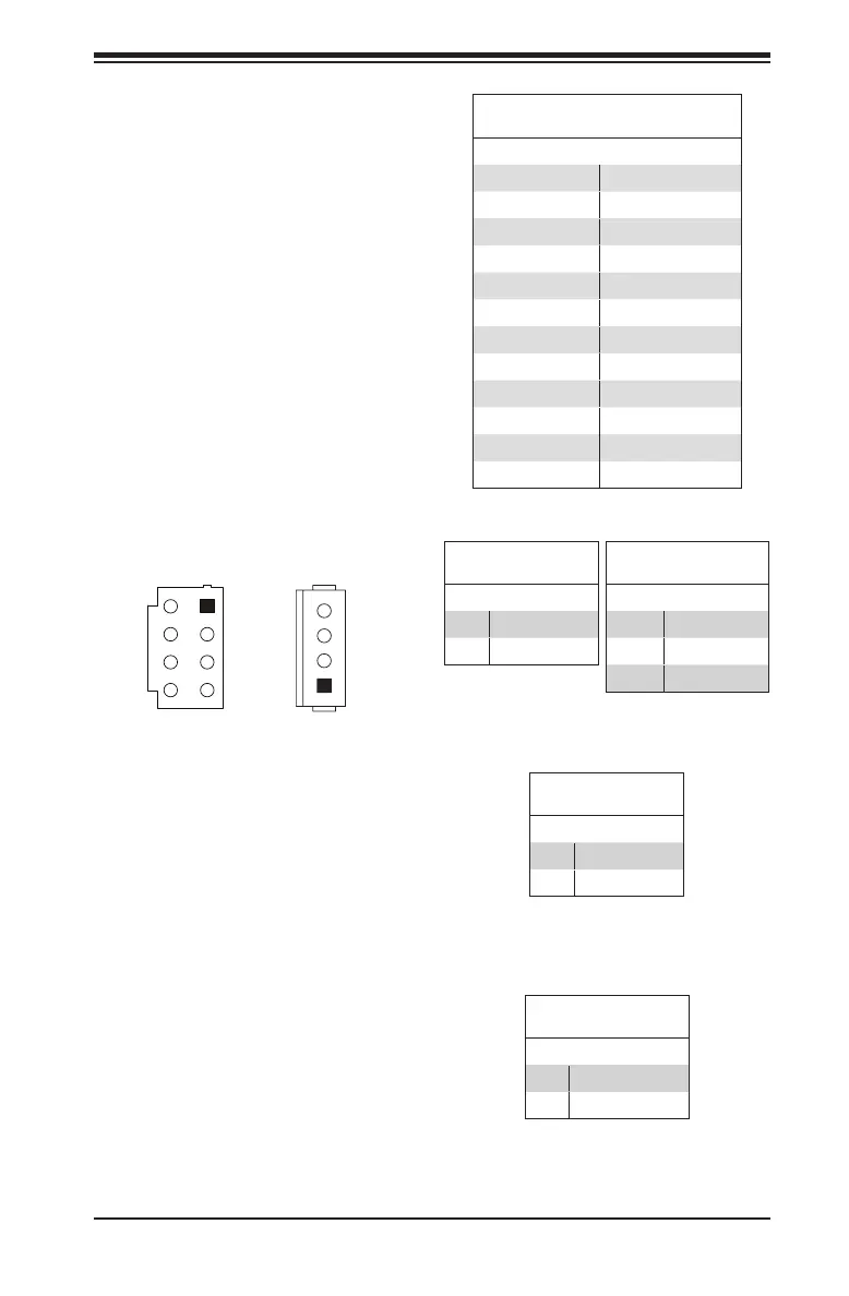
Power Connectors
The 24-pin ATX power connector at
JPW1 is used to provide power to
the motherboard. JPV1 is a 12V DC
power connector that provides alter-
native power for special a enclosure
when the 24-pin ATX power is not in
use. The 4-pin HDD power connector
JPH1 provides power to onboard HDD
devices.
Note: Do not use the 8-pin DC power
at JPV1 when the 24-pin ATX Power
at JPW1 is connected to the power
supply. Do not plug in both JPV1 and
JPW1 at the same time.
Power LED
The Power LED connection is located
on pins 15 and 16 of JF1. Refer to the
Power LED
Pin Denitions (JF1)
15 3.3V
16 PWR LED
4-Pin HDD Power
Pin Denitions (JPH1)
1 12V
2-3 GND
4 5V
8-pin DC Power
Pin Denitions (JPV1)
1-4 GND
5-8 12V
HDD LED
The HDD LED connection is located
on pins 13 and 14 of JF1. Attach a
cable here to indicate the status of all
HDD-related activities. See the table
HDD LED
Pin Denitions (JF1)
13 3.3V Standby
14 HD LED
1
ATX Power 24-pin Connector
Pin Denitions (JPW1)
13 +3.3V 1 +3.3V
14 NC 2 +3.3V
15 COM 3 COM
16 PS_ON 4 +5V
17 COM 5 COM
18 COM 6 +5V
19 COM 7 COM
20 NC 8 PWR_OK
21 +5V 9 5VSB
22 +5V 10 +12V
23 +5V 11 +12V
24 COM 12 +3.3V

 Loading...


