Chapter 5: Advanced Motherboard Setup
5-11
Gigabit Ethernet LAN Ports
Two Gigabit Ethernet ports (LAN1 and LAN2) and a dedicated IPMI LAN port are lo-
cated on the rear I/O panel to provide network connections. These ports accept RJ45
type cables. Please refer to the LED Indicator Section for LAN LED information.
10G SFP+/Ethernet LAN Ports
Two 10 Gigabit SFP+ (Small-form Factor Pluggable) Ethernet LAN ports, supported
by the SoC, are located at LAN7 and LAN8 on the rear I/O panel. Please refer to
the 10G LAN LED section for 10G LAN LED information.
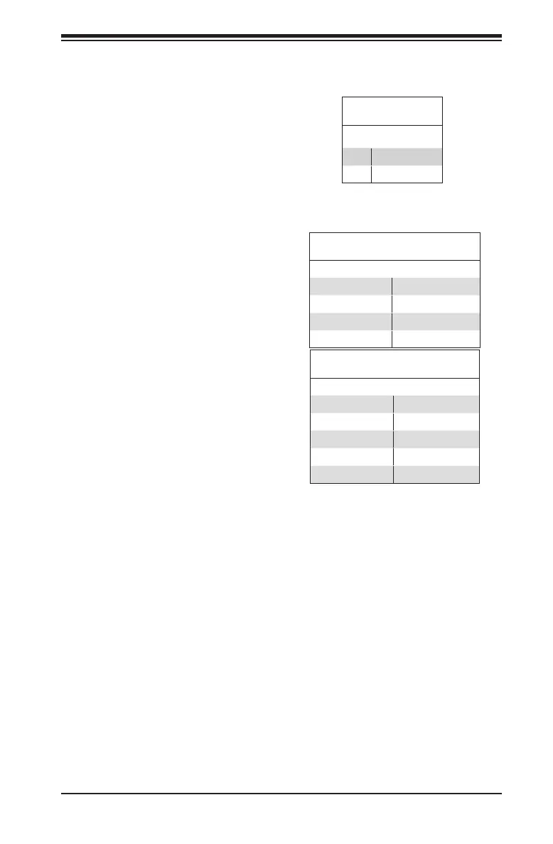
Universal Serial Bus (USB)
Two USB 3.0 ports (USB0/1) are lo-
cated on the I/O back panel. Two USB
2.0 headers (USB3/4 and USB5/6)
and one USB Type-A header are also
provided on the motherboard to pro-
vide front panel access. USB cables
are not included. Refer to the tables
Back Panel USB 3.0
Pin Denitions
1 +5V 5 +5V
2 USB_PN1 6 USB_PN0
3 USB_PP1 7 USB_PP0
4 Ground 8 Ground
Internal USB Port 2.0
Pin Denitions
1 +5V 2 +5V
3 USB_PN2 4 USB_PN3
5 USB_PP2 6 USB_PP3
7 Ground 8 Ground
9 Key 10 NC
Power Button
The Power Button connection is lo-
cated on pins 1 and 2 of JF1. Momen-
tarily contacting both pins will power
on/off the system. This button can be
Instant Off (with a setting in the BIOS
setting, see Chapter 7). Refer to the
Power Button
Pin Denitions (JF1)
1 Signal
2 Ground

 Loading...


