52
SuperServer 1029P-WTRT User's Manual
Universal Serial Bus (USB) Ports
There are four USB 3.0 ports (USB0/1/2/3) located on the I/O back panel. In addition, there is
one USB 3.0 header (USB4/5) on the motherboard to provide front access USB connection.
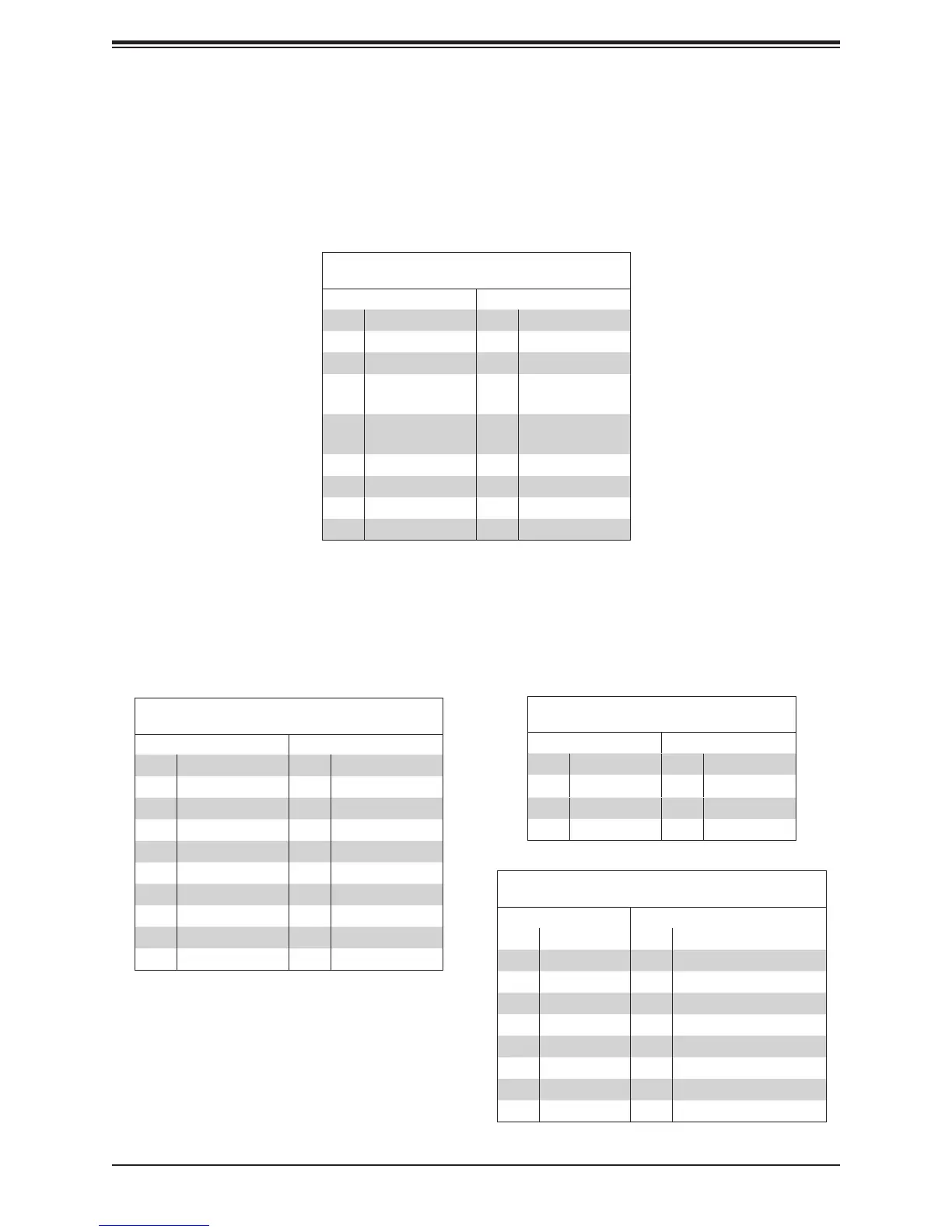
Back Panel USB 0/1 (2.0)
Pin Denitions
Pin# Denition Pin# Denition
1 +5V 5 +5V
2 USB_N 6 USB_N
3 USB_P 7 USB_P
4 Ground 8 Ground
Front Panel USB 4/5 (3.0/2.0)
Pin Denitions
Pin# Denition Pin# Denition
1 VBUS 11 IntA_P2_D+
2 IntA_P1_SSRX- 12 IntA_P2_D-
3 IntA_P1_SSRX+ 13 GND
4 GND 14 IntA_P2_SSTX+
5 IntA_P1_SSTX- 15 IntA_P2_SSTX-
6 IntA_P1_SSTX+ 16 GND
7 GND 17 IntA_P2_SSRX+
8 IntA_P1_D- 18 IntA_P2_SSRX-
9 IntA_P1_D+ 19 VBus
10
ID
Back Panel USB 2/3 (3.0)
Pin Denitions
Pin# Denition Pin# Denition
1 VBUS 10 Power
2 D- 11 USB 2.0 Differential Pair
3 D+ 12
4 Ground 13 Ground of PWR Return
5 StdA_SSRX- 14 SuperSpeed Receiver
6 StdA_SSRX+ 15 Differential Pair
7 GND_DRAIN 16 Ground for Signal Return
8 StdA_SSTX- 17 SuperSpeed Transmitter
9 StdA_SSTX+ 18 Differential Pair
Ethernet Ports
Two LAN ports (LAN1/LAN2) and a dedicated IPMI LAN are located on the I/O back panel.
These LAN ports are supported by the onboard AST 2500 BMC and accepts an RJ45 type
cable. Refer to the LED Indicator Section for LAN LED information.
LAN Ports
Pin Denition
Pin# Denition Pin# Denition
1 10 sgnd
2 TD0+ 11 Act LED
3 TD0- 12 P3V3SB
4
TD1+
13
Link 100 LED
(Yellow, +3V3SB)
5
TD1-
14
Link 1000 LED
(Yellow, +3V3SB)
6 TD2+ 15 Ground
7 TD2- 16 Ground
8 TD3+ 17 Ground
9 TD3- 18 Ground