47
Chapter 4: Motherboard Connections
Control Panel
All JF1 wires have been bundled into a single cable to simplify this connection. Make sure
the red wire plugs into pin 1 as marked on the motherboard. The other end connects to the
control panel PCB board.
M.2 Slot
The X11DDW-NT has one M.2 slot located at JM2_1. M.2 was formerly known as Next
Generation Form Factor (NGFF) and serves to replace mini PCI-E. M.2 allows for a variety of
supports PCI-E 3.0 x4 (32 Gb/s) SSD cards in the 2280 and 22110 form factors.
I-SATA 3.0 and S-SATA 3.0 Ports
The X11DDW-NT has eight I-SATA 3.0 ports (I-SATA0~3, I-SATA4~7) and six S-SATA ports
(S-SATA0~3, S-SATA4, S-SATA5). These SATA ports are supported by the Intel C620 chipset.
S-SATA4/S-SATA5 can be used with Supermicro SuperDOMs which are yellow SATA DOM
connectors with power pins built in, and do not require external power cables. Supermicro
SuperDOMs are backward-compatible with regular SATA HDDs or SATA DOMs that need
external power cables.
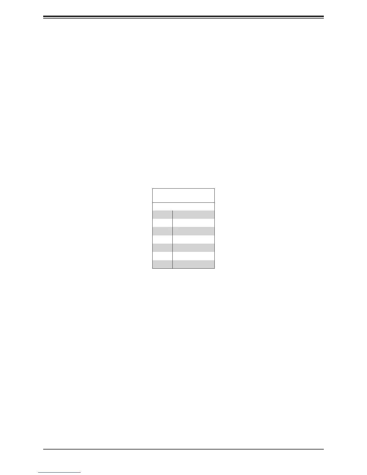
SATA 3.0 Port
Pin Denitions
Pin# Signal
1 Ground
2 SATA_TXP
3 SATA_TXN
4 Ground
5 SATA_RXN
6 SATA_RXP
7 Ground