48
SuperServer 1029P-WTRT User's Manual
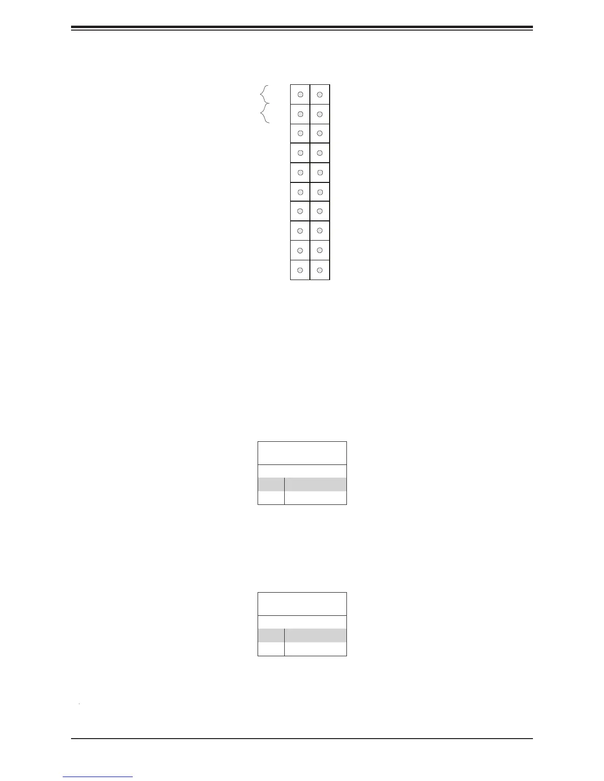
Figure 4-1. JF1: Control Panel Pins
Power Button
OH/Fan Fail LED
1
Reset Button
2
Power Fail
HDD LED
Power LED
Reset
PWR
UID LED
Ground
Ground
19 20
3.3V
X
Ground
NMI
X
NIC2 Activity LED
3.3V Stby
3.3V Stby
3.3V Stby
NIC1 Activity LED
3.3V
Reset Button
Pin Denitions (JF1)
Pins Denition
3 Reset
4 Ground
Power Button
Pin Denitions (JF1)
Pins Denition
1 Signal
2 Ground
Power Button
The Power Button connection is located on pins 1 and 2 of JF1. Momentarily contacting both
button (with a setting in the BIOS - see Chapter 4). To turn off the power when the system
is in suspend mode, press the button for 4 seconds or longer. Refer to the table below for
Reset Button
The Reset Button connection is located on pins 3 and 4 of JF1. Attach it to a hardware reset