2-22
X7DCU User's Manual
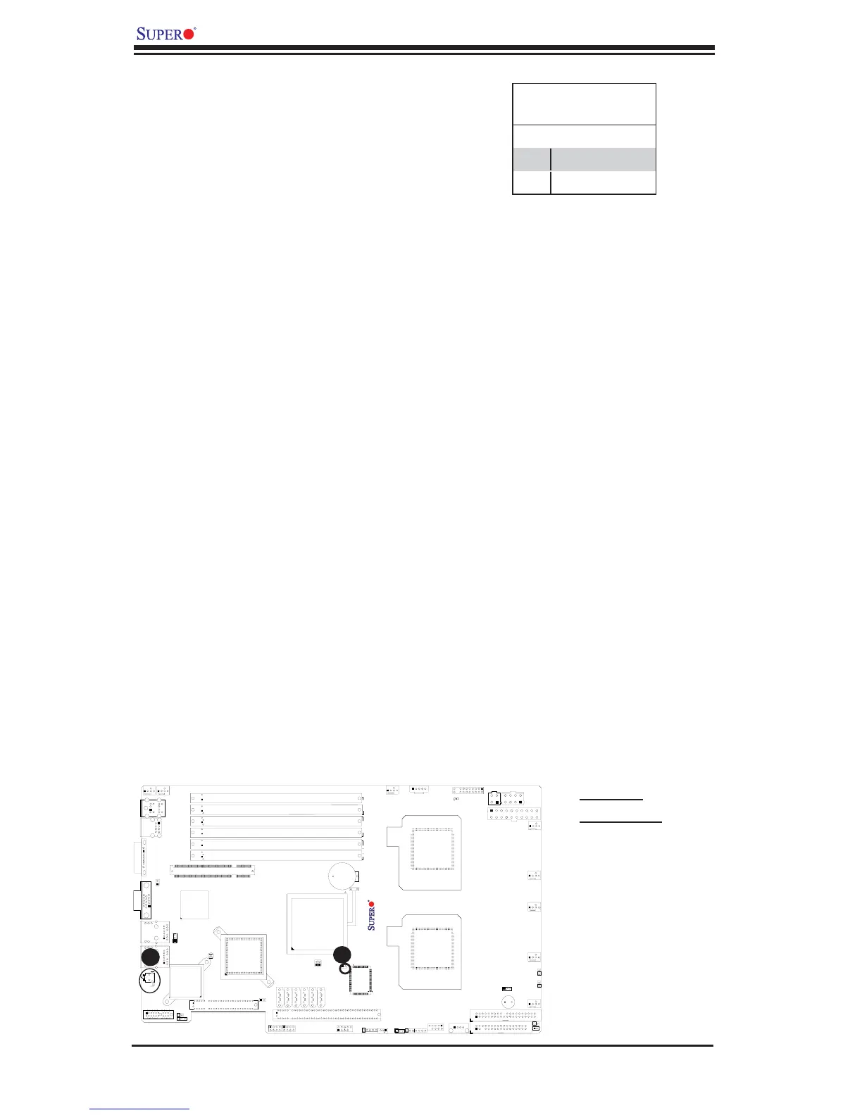
LE2
SW1
JD1
JBT1
JWOR1
JL1
JOH1
JCF1
JK1
JPEW2
JP6
JP7
JPL1
JWD1
JIDE
FAN6
FAN5
FAN7
JWF1
I-SATA0
CPU2
CPU1
SXB2:PCI-E X8
UIOP
BANK3
JWOL
SGPIO2
SGPIO1
COM2
CPU FAN1
KB/MS
SMBUS_PS
COM1
USB0/1
BANK2
LAN1
VGA
BANK1
DIMM1C
DIMM2B
DIMM1A
DIMM1B
DIMM2A
LAN2
CPU FAN2
Compact Flash
IDE
Floppy
SXB1:PCI-E X16
USB 4
USB 2/3
JPEW1
Battery
DIMM2C
SIMSO IPMI
VGA CTRL
LAN CTRL
Intel 5100
North Bridge
Intel ICH9R
South Bridge
USB5
LE19
X7DCU
S I/O
I-SATA1
I-SATA2
I-SATA3
I-SATA4
I-SATA5
Buzzer
JF1
JPW1
JPW2
JPW3
FAN1
FAN2
FAN3
FAN8
FAN4
JPG1
A
A. Keylock
B. UID/Switch
B
Keylock
The keyboard lock connection is desig-
nated JK1. Utilizing this header allows
you to inhibit any actions made on the
keyboard, effectively "locking" it.
Keylock
Pin Defi nitions
Pin# Defi nition
1 Ground
2 Keylock R-N
Unit Identifi cation Switches
There are two Unit Identifi cation (UID)
switches on the motherboard. The Front
Panel UID switch is connected to Pin 13
of the Front Control Panel. The Rear
UID switch (SW1) is located next to LAN
Port2. When you push the UID switch on
the Front Control Panel, you will turn on
both the Rear and the Front Panel UID
indicator. Press the Front Panel or the
Rear UID switch again to turn off the UID
Indicators. The UID LED (LE2) works in
conjunction with the UID switches. Press
the UID switches to turn on and off the
UID LED Indicators. The UID Switches
and the UID LED Indicators provide easy
identifi cation of a system unit that may be
in need of service. (For more information
on the FP UID Switch, please refer to
FP UID Switch on Page 2-11.)
 Loading...


