Chapter 2: Installation
2-25
LE2
SW1
JD1
JBT1
JWOR1
JL1
JOH1
JCF1
JK1
JPEW2
JP6
JP7
JPL1
JWD1
JIDE
FAN6
FAN5
FAN7
JWF1
I-SATA0
CPU2
CPU1
SXB2:PCI-E X8
UIOP
BANK3
JWOL
SGPIO2
SGPIO1
COM2
CPU FAN1
KB/MS
SMBUS_PS
COM1
USB0/1
BANK2
LAN1
VGA
BANK1
DIMM1C
DIMM2B
DIMM1A
DIMM1B
DIMM2A
LAN2
CPU FAN2
Compact Flash
IDE
Floppy
SXB1:PCI-E X16
USB 4
USB 2/3
JPEW1
Battery
DIMM2C
SIMSO IPMI
VGA CTRL
LAN CTRL
Intel 5100
North Bridge
Intel ICH9R
South Bridge
USB5
LE19
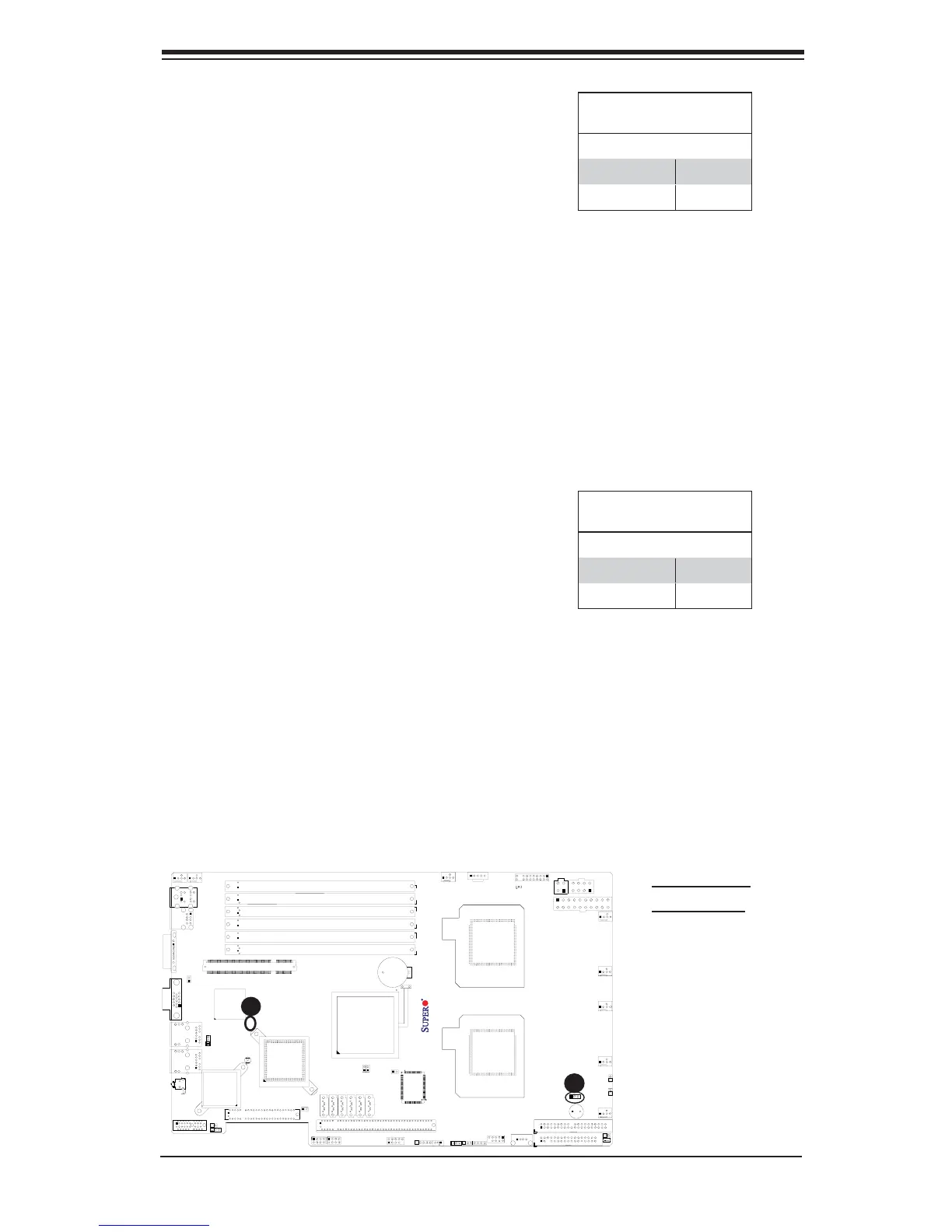
X7DCU
S I/O
I-SATA1
I-SATA2
I-SATA3
I-SATA4
I-SATA5
Buzzer
JF1
JPW1
JPW2
JPW3
FAN1
FAN2
FAN3
FAN8
FAN4
JPG1
A. VGA Enable
B. IDE Enable
A
B
VGA Enable/Disable
Jumper Settings (JPG1)
Both Jumpers Defi nition
*Pins 1-2 Enabled
Pins 2-3 Disabled
VGA Enable/Disable
JPG1 allows you to enable or disable the
VGA port. The default position is on pins
1 and 2 to enable VGA. See the table on
the right for jumper settings.
IDE Enable/Disable
Jumper Settings
Both Jumpers Defi nition
*Pins 1-2 Enabled
Pins 2-3 Disabled
IDE Enable/Disable
JIDE allows you to enable or disable the
IDE slot. The default position is on pins
1 and 2 to enable the IDE slot. See the
table on the right for jumper settings.