Chapter 2: Installation
2-27
LE2
SW1
JD1
JBT1
JWOR1
JL1
JOH1
JCF1
JK1
JPEW2
JP6
JP7
JPL1
JWD1
JIDE
FAN6
FAN5
FAN7
JWF1
I-SATA0
CPU2
CPU1
SXB2:PCI-E X8
UIOP
BANK3
JWOL
SGPIO2
SGPIO1
COM2
CPU FAN1
KB/MS
SMBUS_PS
COM1
USB0/1
BANK2
LAN1
VGA
BANK1
DIMM1C
DIMM2B
DIMM1A
DIMM1B
DIMM2A
LAN2
CPU FAN2
Compact Flash
IDE
Floppy
SXB1:PCI-E X16
USB 4
USB 2/3
JPEW1
Battery
DIMM2C
SIMSO IPMI
VGA CTRL
LAN CTRL
Intel 5100
North Bridge
Intel ICH9R
South Bridge
USB5
LE19
X7DCU
S I/O
I-SATA1
I-SATA2
I-SATA3
I-SATA4
I-SATA5
Buzzer
JF1
JPW1
JPW2
JPW3
FAN1
FAN2
FAN3
FAN8
FAN4
JPG1
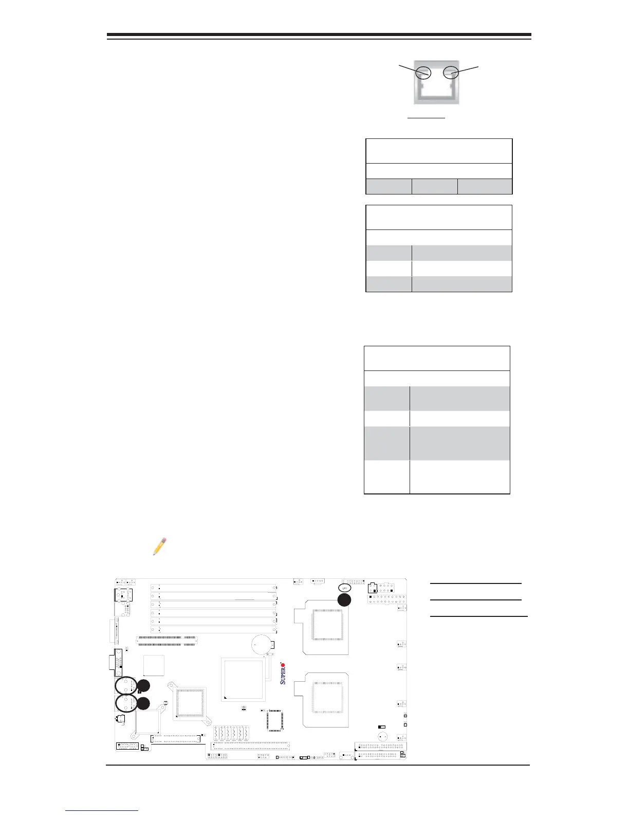
GLAN LEDs
There are two GLAN ports on the moth-
erboard. Each Gigabit Ethernet LAN port
has two LEDs. The yellow LED indicates
activity, while the Link LED may be
green, amber or off to indicate the speed
of the connection. See the tables at right
for more information.
2-7 Onboard Indicators
C
A. GLAN Port1 LEDs
B. GLAN Port2 LEDs
C. Onboard PWR LED
Activity
LED
GLAN Link Indicator
LED Settings
LED Color Defi nition
Off No Connection or 10 Mbps
Green 100 Mbps
Amber 1 Gbps
Link
LED
GLAN Activity Indicator
LED Setting
Color Status Defi nition
Yellow Flashing LAN Active
Rear View
(when viewing from the back of the chassis.)
A
B
Onboard Power LED
An Onboard Power LED is located at
LE19 on the motherboard. When this LED
Indicator is on, the system is on. Be sure
to unplug the power cable before remov-
ing or adding any components. See the
table on the right for more details.
Onboard PWR LED Indicator
LED Settings
LED Color Defi nition
Off System Off (*PWR cable
not connected)
Green System On
Green:
Flashing
Quickly
ACPI S1 State
Green:
Flashing
Slowly
ACPI S3 (STR) State
For UID LED Indicator (LE2), please refer to Page 2-11 and Page 2-22.