Chapter 2: Installation
2-23
LE2
SW1
JD1
JBT1
JWOR1
JL1
JOH1
JCF1
JK1
JPEW2
JP6
JP7
JPL1
JWD1
JIDE
FAN6
FAN5
FAN7
I-SATA0
CPU2
CPU1
SXB2:PCI-E X8
UIOP
BANK3
JWOL
SGPIO2
SGPIO1
COM2
CPU FAN1
KB/MS
SMBUS_PS
COM1
USB0/1
BANK2
LAN1
VGA
BANK1
DIMM1C
DIMM2B
DIMM1A
DIMM1B
DIMM2A
LAN2
CPU FAN2
Compact Flash
IDE
SXB1:PCI-E X16
USB 4
USB 2/3
JPEW1
Battery
DIMM2C
SIMSO IPMI
VGA CTRL
LAN CTRL
Intel 5100
North Bridge
Intel ICH9R
South Bridge
USB5
LE19
X7DCU
S I/O
I-SATA1
I-SATA2
I-SATA3
I-SATA4
I-SATA5
Buzzer
JF1
JPW1
JPW2
JPW3
FAN1
FAN2
FAN3
FAN8
FAN4
JPG1
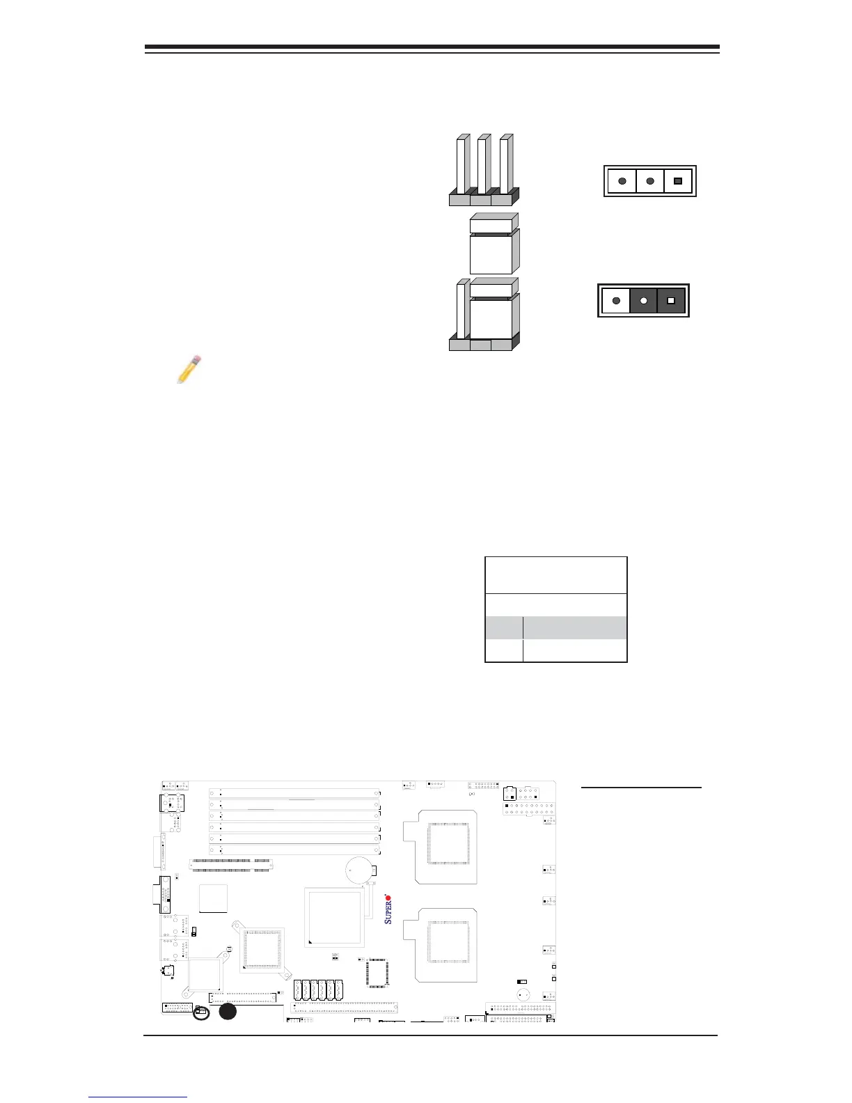
2-6 Jumper Settings
Explanation of Jumpers
To modify the operation of the mother-
board, jumpers can be used to choose
between optional settings. Jumpers
create shorts between two pins to
change the function of the connector.
Pin 1 is identifi ed with a square solder
pad on the printed circuit board. See
the motherboard layout pages for
jumper locations.
Note: On two pin jumpers,
"Closed" means the jumper is on and
"Open" means the jumper is off the
pins.
Connector
Pins
Jumper
Cap
Setting
Pin 1-2 short
3 2 1
3 2 1
GLAN Enable/Disable
JPL1 enables or disables GLAN
Port1/GLAN Port2 on the mother-
board. See the table on the right for
jumper settings. The default setting is
Enabled.
GLAN Enable
Jumper Settings
Pin# Defi nition
1-2 Enabled (default)
2-3 Disabled
A. GLAN 1/2 Enable
A