2-18
Supermicro C7B250-CB-MK Motherboard User’s Manual
JTPM1
RST
PWR
ON
XOH/FF
X
NIC
1
PWR
LED
HDD
LED
JF1
USB 2/3USB 8/9(3.0)
2-3:BIOS RECOVERY
1-2:NORMAL
JBR1
WATCH DOG
1-2:RST
2-3:NMI
JWD1:
JBR1
JPME2
AUDIO FP
COM1
JD1:SPEAKER :1-4
JD1
JSD1
JWD1
JL1
JL1:
CHASSIS
INTRUSION
2-3:ME MANUFACTURING MODE
JPME2:
1-2:NORMAL
I-SATA5
I-SATA4
I-SATA3
I-SATA2
I-SATA1
I-SATA0
PCH SLOT1 PCI-E 3.0 X1
JBT1
PCH SLOT2 PCI-E 3.0 X4
J9702
JSTBY1
J9701
JI2C1
JI2C2
JSPDIF_OUT
5V STBY POWER
JSTBY1:
CPU SLOT3 PCI-E 3.0 X16
OFF:DISABLE
JI2C1/JI2C2
ON :ENABLE
HD AUDIO
PCIE M.2
CONNECTOR 1
SYS_FAN2
USB 6/7(3.0)
LAN
CPU
JPW1
DVI
JPUSB1:USB0/1 WAKE UP
HDMI/DP
DIMMB2
DIMMA2
2-3 DISABLE
1-2 ENABLE
CPU_FAN1
JVR1
JPUSB1
JPW2
KB/MOUSE
LED1
REV: 1.00
C7B250-CB-MK
DESIGNED IN USA
+
MAC CODE
BAR CODE
BIOS LICENSE
C
A
+
USB 4/5
(3.0)
USB 0/1
B1
2280
2260
2242
SYS_FAN1
JCMOS
MH10
MH11
MH12
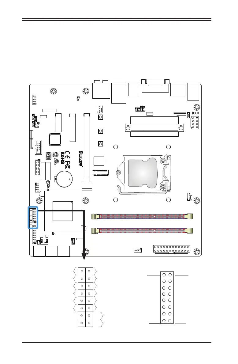
Front Control Panel
JF1 contains header pins for various buttons and indicators that are
normally located on a control panel at the front of the chassis. These
connectors are designed specically for use with Supermicro chassis. See
the gure below for the descriptions of the front control panel buttons
and LED indicators. Refer to the following section for descriptions and
pin denitions.
Pin 15Pin 16
Pin 1
Pin 2
JF1 Header Pins
Power Button
ED (-)
1
NIC1 LED (-)
Reset Button
2
HDD LED (-)
POWER LED (-)
Reset
PWR
POWER LED (+)
Ground
Ground
X
X
HDD LED (+)
NIC1 LED (+)
Over heat/Fan Fail L
X
X