Chapter 2: Installation
2-19
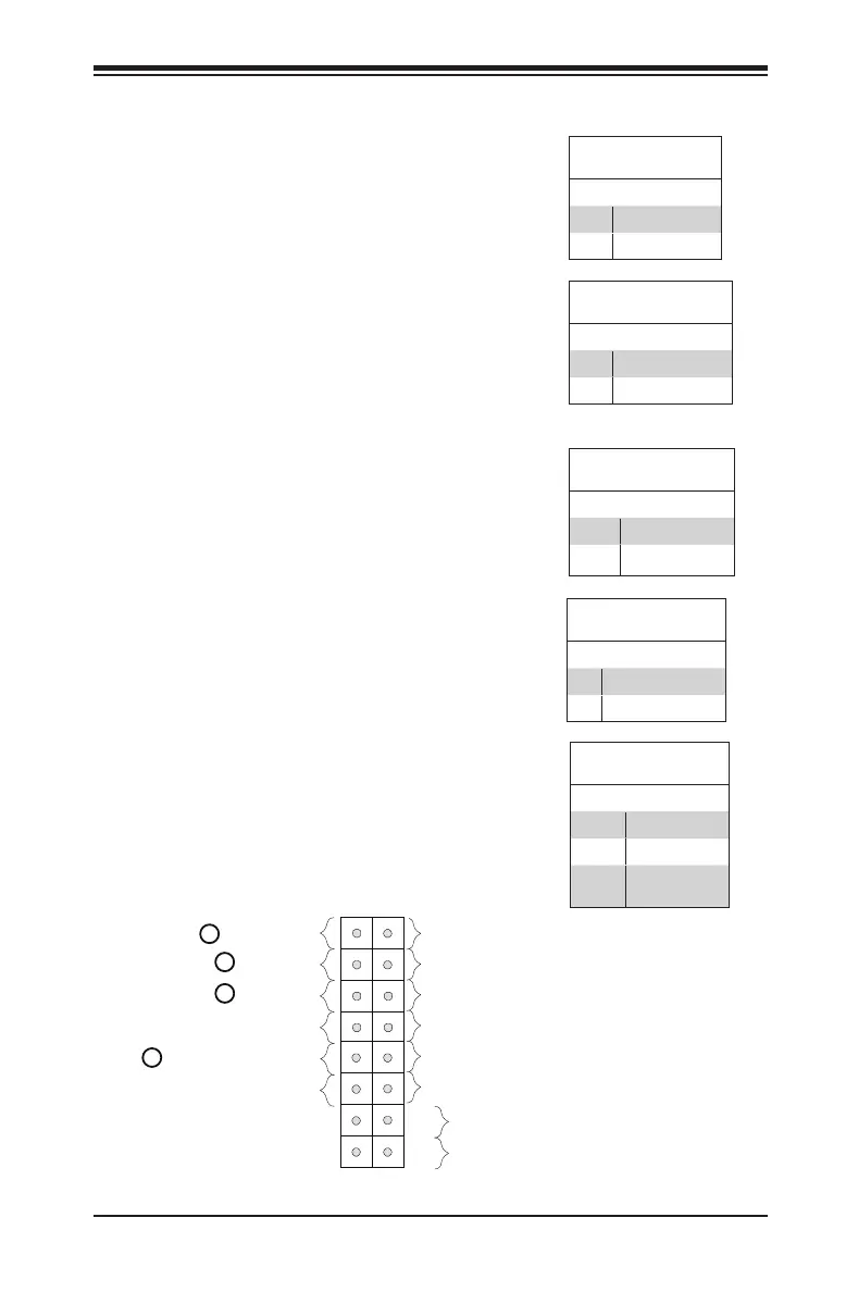
Power Button
ED (-)
1
NIC1 LED (-)
Reset Button
2
HDD LED (-)
POWER LED (-)
Reset
PWR
POWER LED (+)
Ground
Ground
X
X
HDD LED (+)
NIC1 LED (+)
Over heat/Fan Fail L
X
X
Front Control Panel Pin Definitions
Power LED
The Power LED connection is located on
pins 15 and 16 of JF1. Refer to the table
on the right for pin denitions.
Power LED
Pin Denitions (JF1)
Pin# Denition
15 +5V
16 Ground
A. PWR LED
B. HDD LED
C. NIC1 LED
D. OH/Fan Fail LED
HDD LED
The HDD LED connection is located on
pins 13 and 14 of JF1. Attach a cable
here to indicate the status of HDD-
related activities, including IDE, SATA
activities. See the table on the right for
pin denitions.
HDD LED
Pin Denitions (JF1)
Pin# Denition
13 +5V
14 HD Active
NIC1 (LAN)
The NIC (Network Interface Controller)
LED connection for LAN port 1 is located
on pins 11 and 12 of JF1. Attach an LED
indicator to this header to display net-
work activity. Refer to the table on the
right for pin denitions.
LAN LED
Pin Denitions (JF1)
Pin# Denition
11 Vcc
12 Ground
Overheat (OH)/Fan Fail
Connect an LED cable to OH/Fan Fail
connections on pins 7 and 8 of JF1 to
provide warnings for chassis overheat/
fan failure. Refer to the table on the right
for pin denitions.
OH/Fan Fail LED
Pin Denitions (JF1)
Pin# Denition
7 Vcc/Blue UID LED
8 OH/Fan Fail LED
OH/Fan Fail Indicator
Status
State Denition
Off Normal
On Overheat
Flash-
ing
Fan Fail
A
B
C
D