Chapter 2: Installation
2-25
JTPM1
RST
PWR
ON
XOH/FF
X
NIC
1
PWR
LED
HDD
LED
JF1
USB 2/3USB 8/9(3.0)
2-3:BIOS RECOVERY
1-2:NORMAL
JBR1
WATCH DOG
1-2:RST
2-3:NMI
JWD1:
JBR1
JPME2
AUDIO FP
COM1
JD1:SPEAKER :1-4
JD1
JSD1
JWD1
JL1
JL1:
CHASSIS
INTRUSION
2-3:ME MANUFACTURING MODE
JPME2:
1-2:NORMAL
I-SATA5
I-SATA4
I-SATA3
I-SATA2
I-SATA1
I-SATA0
PCH SLOT1 PCI-E 3.0 X1
JBT1
PCH SLOT2 PCI-E 3.0 X4
J9702
JSTBY1
J9701
JI2C1
JI2C2
JSPDIF_OUT
5V STBY POWER
JSTBY1:
CPU SLOT3 PCI-E 3.0 X16
OFF:DISABLE
JI2C1/JI2C2
ON :ENABLE
HD AUDIO
PCIE M.2
CONNECTOR 1
SYS_FAN2
USB 6/7(3.0)
LAN
CPU
JPW1
DVI
JPUSB1:USB0/1 WAKE UP
HDMI/DP
DIMMB2
DIMMA2
2-3 DISABLE
1-2 ENABLE
CPU_FAN1
JVR1
JPUSB1
JPW2
KB/MOUSE
LED1
REV: 1.00
C7B250-CB-MK
DESIGNED IN USA
+
MAC CODE
BAR CODE
BIOS LICENSE
C
A
+
USB 4/5
(3.0)
USB 0/1
B1
2280
2260
2242
SYS_FAN1
JCMOS
MH10
MH11
MH12
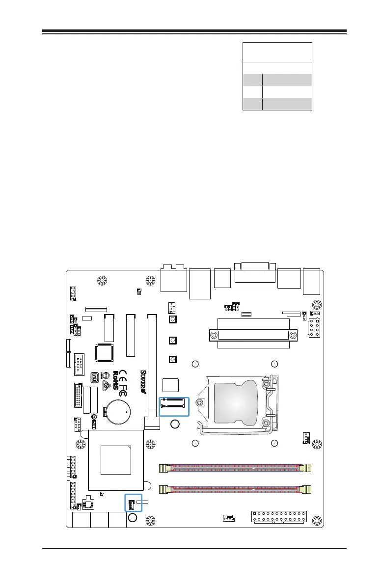
A. Standby Power
B. PCI-E M.2 Connector
Standby Power Header
The Standby Power header is located at
JSTBY1 on the motherboard. See the
table on the right for pin denitions.
Standby Power
Pin Denitions
Pin# Denition
1 +5V Standby
2 Ground
3 Wake-up
PCI-E M.2 Connector
The PCI-E M.2 connector is for PCI-E
memory devices. These devices must
conform to the PCIE M.2 specications
(formerly known as NGFF).
A
B