USB 4/5(3.0)
USB 2/3
USB 0/1
PCH SLOT2 PCI-E 3.0 X1
NMI
USB 16/17(3.0)
CPU SLOT1 PCI-E 3.0 X8 (IN X16)
CPU SLOT7 PCI-E 3.0 X16
PWR LEDHDD LED XPWR ON OH/FF NIC1NIC2RST X
CPU SLOT3 PCI-E 3.0 X8 (IN X16)
CPU SLOT5 PCI-E 3.0 X8 (IN X16)
I-SATA2
I-SATA0
DIMMA1
DIMMB2
DIMMB1
DIMMA2
1-2 ENABLE
2-3 DISABLE
JPAC1:AUDIO
HD AUDIO
USB 8/9 (3.1)
LAN2
LAN1
USB 6/7(3.1)
DIMMD2
DIMMD1
DIMMC2
DIMMC1
VGA
KB/Mouse
CLOSE 1st
OPEN 1st
JF1
LGA2066
J*
LED1
JRK1
SP1
JTPM1
JPI2C1
JL1
JPAC1
JWD1
JPG1
JPME2
FAN5
FAN3
FAN2
FAN4
FAN1
JBT1
JSD1
JIPMB1
JSTBY1
MH15
MH12
MH14
JD1
J3701
LED6903
LED6904
LED7201
B2
JPW1
JPW2
JCOM1
PCH
LAN
CTRL
RESET
POWER
JPW3
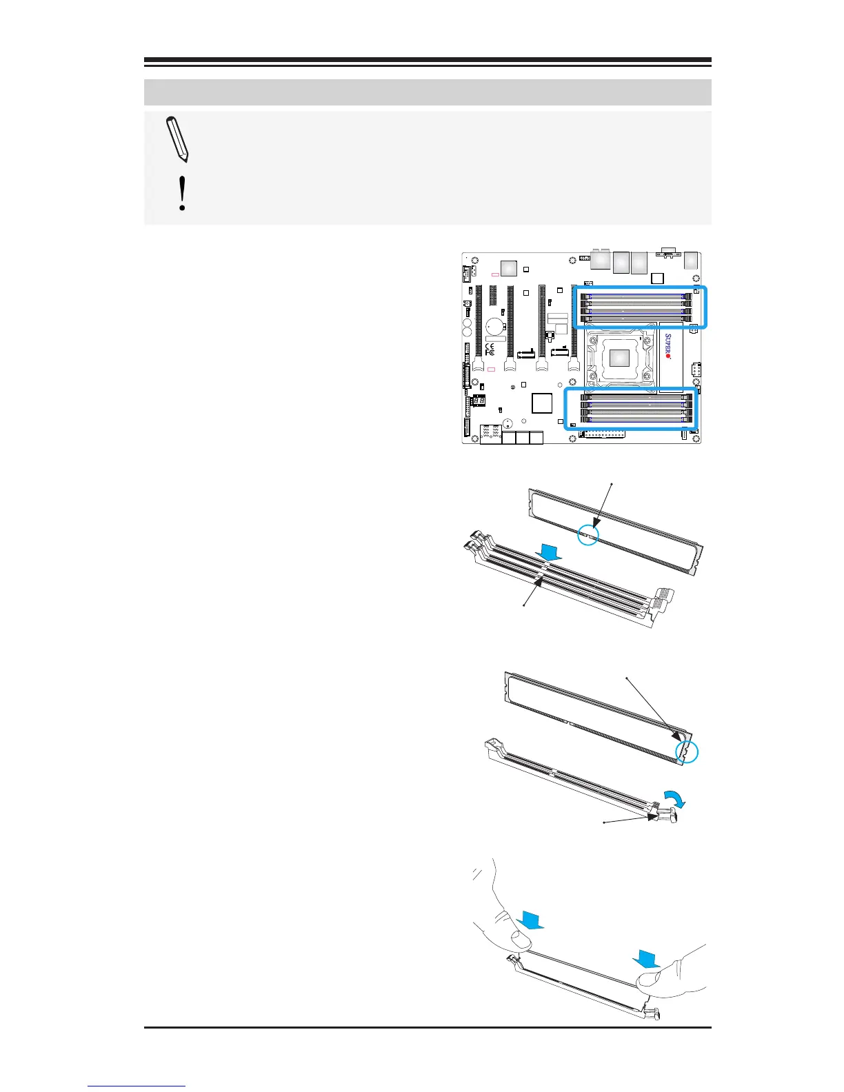
2-4 Installing DDR4 Memory
Note: Check the Supermicro website for recommended memory
modules.
Attention! Exercise extreme care when installing or removing
DIMM modules to prevent any possible damage.
DIMM Installation
1. Insert the desired number of
DIMMs into the memory slots,
starting with DIMMA1, DIMMB1,
DIMMC1, DIMMD1, then
DIMMA2, DIMMB2. DIMMC2,
DIMMD2. For the system to
work properly, please use the
memory modules of the same
type and speed.
2. Align the DIMM module key
with the receptive point on the
single-latch DIMM slot.
3. Push the release tab outward to
unlock the slot.
4. Align the notch on the end of
the module against the recep-
tive point on the end of the slot.
5. Press both ends of the module
straight down into the slot until
the module snaps into place.
6. Push the release tab to the lock
position to secure the module
into the slot.
Removing Memory Modules
Reverse the steps above to remove
the DIMM modules from the moth-
erboard.
Release Tab
Notch
Press both notches
straight down into
the memory slot.
Module Key
Receptive Point


 To Next Page