Chapter 2: Installation
2-23
BIOS
LICENSE
MAC CODE
IPMI CODE
BAR CODE
C9X299-PG REV:1.01
+
1
+
PRESS FIT
PCIE M.2 CONNECTOR 2
PCIE M.2 CONNECTOR 1
SPEAKER:1-4
BUZZER:3-4
JD1
CLEAR CMOS
U.2 CONNECTOR 1
U.2 CONNECTOR 2
I-SATA5
I-SATA4
I-SATA3
USB 4/5(3.0)
USB 2/3
USB 0/1
PCH SLOT2 PCI-E 3.0 X1
NMI
USB 16/17(3.0)
CPU SLOT1 PCI-E 3.0 X8 (IN X16)
CPU SLOT7 PCI-E 3.0 X16
PWR LEDHDD LED XPWR ON OH/FF NIC1NIC2RST X
CPU SLOT3 PCI-E 3.0 X8 (IN X16)
CPU SLOT5 PCI-E 3.0 X8 (IN X16)
I-SATA2
I-SATA0
I-SATA1
DIMMA1
DIMMB2
DIMMB1
DIMMA2
1-2 ENABLE
2-3 DISABLE
JPAC1:AUDIO
HD AUDIO
USB 8/9 (3.1)
LAN2
LAN1
USB 6/7(3.1)
DIMMD2
DIMMD1
DIMMC2
DIMMC1
VGA
KB/Mouse
CLOSE 1st
OPEN 1st
JF1
LGA2066
J*
LED1
JRK1
SP1
JTPM1
JPI2C1
JL1
JPAC1
JWD1
JPG1
JPME2
FAN5
FAN3
FAN2
FAN4
FAN1
JBT1
JSD1
JIPMB1
JSTBY1
MH15
MH12
MH14
JD1
J3701
LED6903
LED6904
LED7201
B2
JPW1
JPW2
JCOM1
PCH
LAN
CTRL
RESET
POWER
JPW3
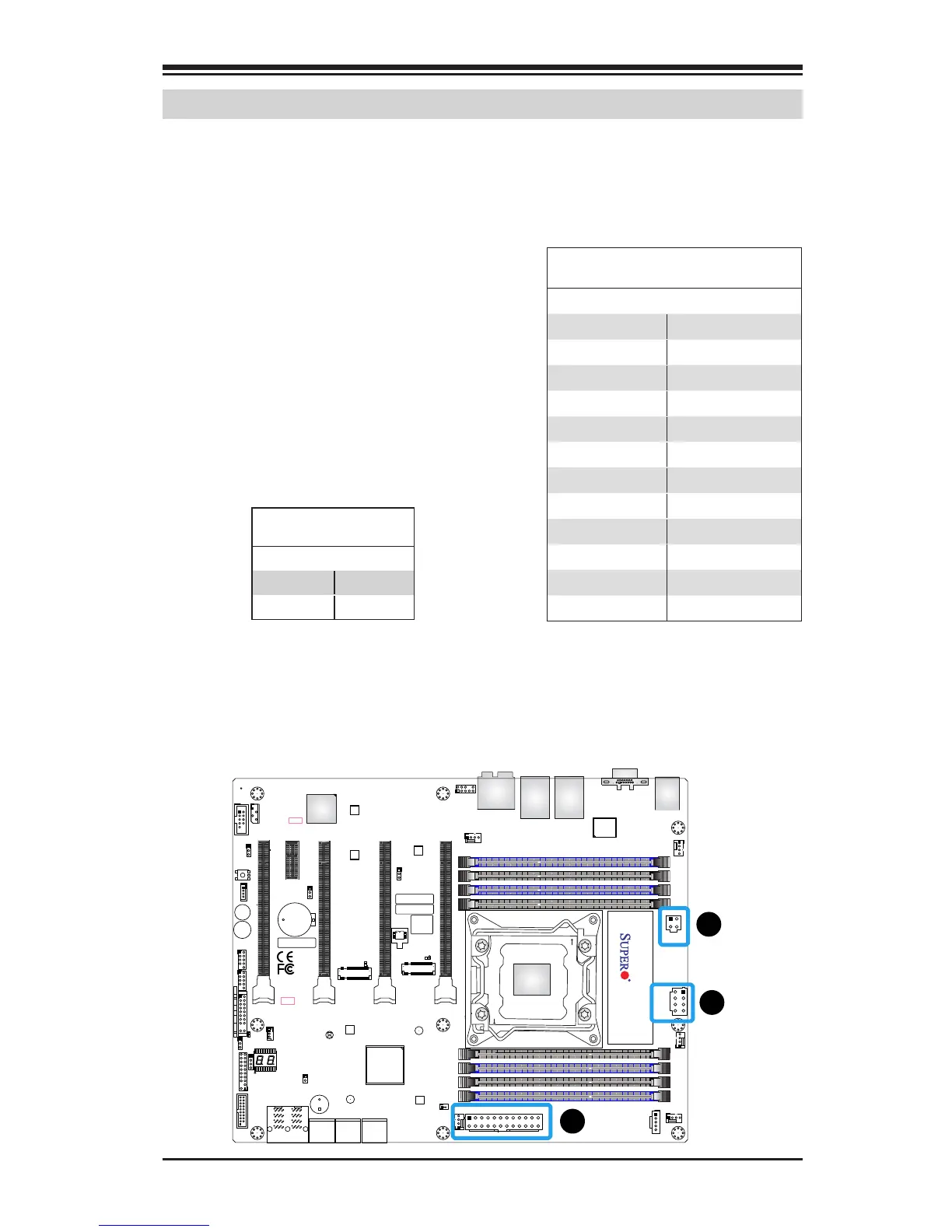
2-8 Connecting Cables
This section provides brief descriptions and pin-out denitions for on-
board headers and connectors. Be sure to use the correct cable for each
header or connector.
A. 24-Pin ATX Main PWR
B. 8-Pin PWR
C. 4-pin PWR
ATX Power 24-pin Connector
Pin Denitions (JPW1)
Pin# Denition Pin # Denition
13 +3.3V 1 +3.3V
14 -12V 2 +3.3V
15 COM 3 COM
16 PS_ON 4 +5V
17 COM 5 COM
18 COM 6 +5V
19 COM 7 COM
20 Res (NC) 8 PWR_OK
21 +5V 9 5VSB
22 +5V 10 +12V
23 +5V 11 +12V
24 COM 12 +3.3V
(Required)
12V 8-pin Power Connec-
tor Pin Denitions
Pins Denition
1 through 4 Ground
5 through 8 +12V
ATX Main PWR and CPU PWR
Connectors
The 24-pin main power connector
(JPW1) provides power to the mother-
board. The 4-pin and 8-pin CPU PWR
connectors (JPW2, JPW3) are also re-
quired for the processor. These power
connectors meet the SSI EPS 12V speci-
cation. Refer to the table on the right
for pin denitions.
B
A
C


 To Next Page