Chapter 2: Installation
2-19
BIOS
LICENSE
MAC CODE
IPMI CODE
BAR CODE
C9X299-PG REV:1.01
+
1
+
PRESS FIT
PCIE M.2 CONNECTOR 2
PCIE M.2 CONNECTOR 1
SPEAKER:1-4
BUZZER:3-4
JD1
CLEAR CMOS
U.2 CONNECTOR 1
U.2 CONNECTOR 2
I-SATA5
I-SATA4
I-SATA3
USB 4/5(3.0)
USB 2/3
USB 0/1
PCH SLOT2 PCI-E 3.0 X1
NMI
USB 16/17(3.0)
CPU SLOT1 PCI-E 3.0 X8 (IN X16)
CPU SLOT7 PCI-E 3.0 X16
PWR LEDHDD LED XPWR ON OH/FF NIC1NIC2RST X
CPU SLOT3 PCI-E 3.0 X8 (IN X16)
CPU SLOT5 PCI-E 3.0 X8 (IN X16)
I-SATA2
I-SATA0
I-SATA1
DIMMA1
DIMMB2
DIMMB1
DIMMA2
1-2 ENABLE
2-3 DISABLE
JPAC1:AUDIO
HD AUDIO
USB 8/9 (3.1)
LAN2
LAN1
USB 6/7(3.1)
DIMMD2
DIMMD1
DIMMC2
DIMMC1
VGA
KB/Mouse
CLOSE 1st
OPEN 1st
JF1
LGA2066
J*
LED1
JRK1
SP1
JTPM1
JPI2C1
JL1
JPAC1
JWD1
JPG1
JPME2
FAN5
FAN3
FAN2
FAN4
FAN1
JBT1
JSD1
JIPMB1
JSTBY1
MH15
MH12
MH14
JD1
J3701
LED6903
LED6904
LED7201
B2
JPW1
JPW2
JCOM1
PCH
LAN
CTRL
RESET
POWER
JPW3
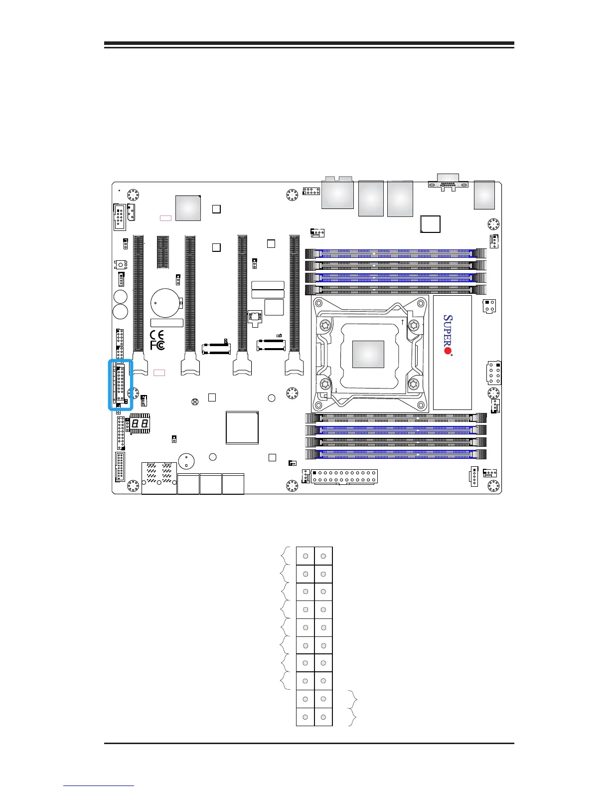
Front Control Panel
JF1 contains header pins for various buttons and indicators that are
normally located on a control panel at the front of the chassis. These
connectors are designed specically for use with Supermicro chassis. See
the gure below for the descriptions of the front control panel buttons
and LED indicators. Refer to the following section for descriptions and
pin denitions.
JF1 Header Pins
Power Button
1
NIC1 LED
Reset Button
2
HDD LED
Power LED
#3-4
Ground
Ground
1920
NIC2 LED
X
NMI
Ground
OH/Fan Fail LED
Vcc
X
Power Fail LED
Vcc
Vcc
Vcc
Vcc
#1-2
Vcc


 To Next Page