2-36
Supermicro C9X299-PG/-PGF/-RPGF Motherboard User’s Manual
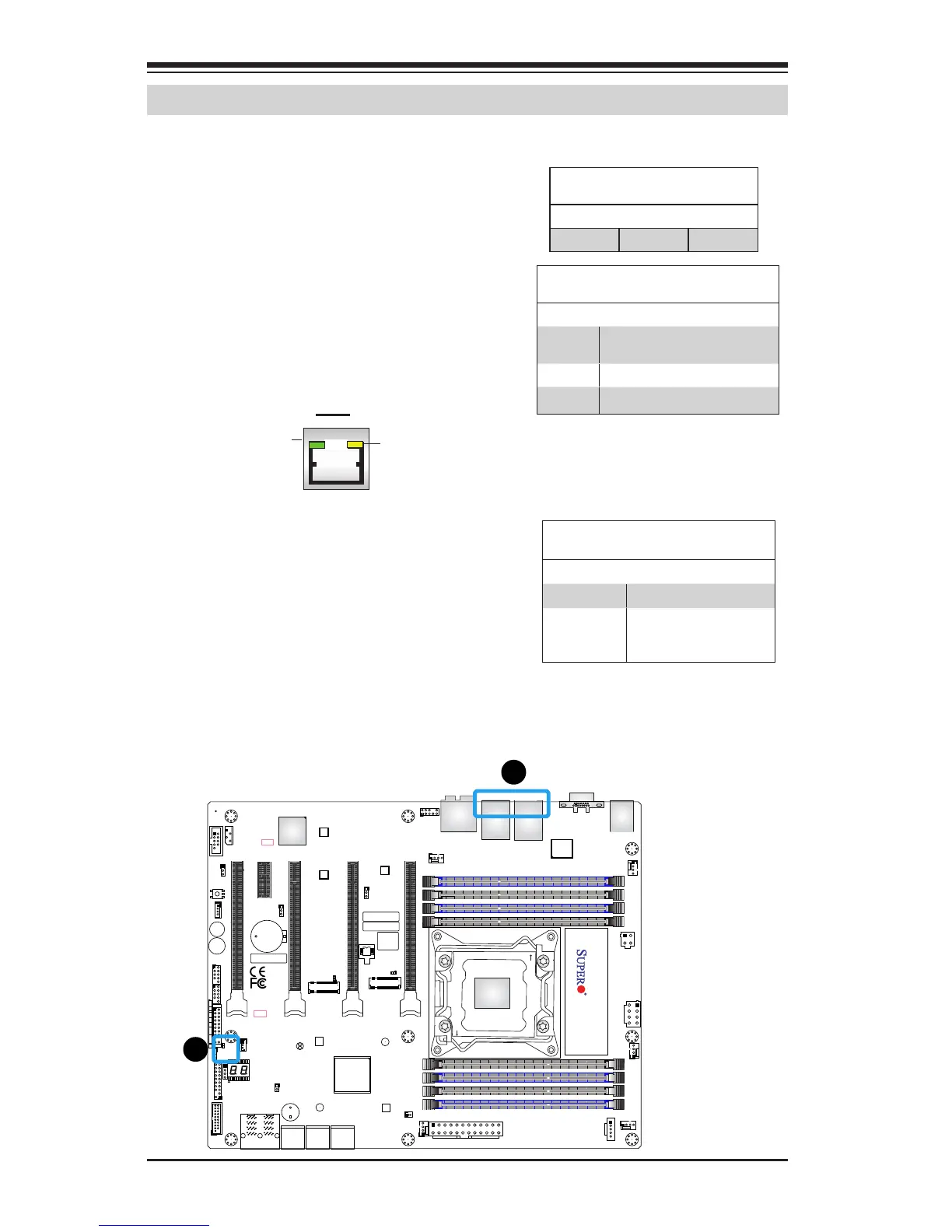
A. LAN LEDs
B. Onboard Power LED
LAN LEDs
Two LAN ports are on the I/O back
panel. These Ethernet LAN ports have
two LEDs (Light Emitting Diode). The
yellow LED indicates activity, while the
Link LED may be green, amber, or off to
indicate the speed of the connections.
Refer to the tables on the right for more
information.
2-10 Onboard Indicators
LAN
Activity LED
Link LED
Onboard PWR LED Indicator
LED Status
Status Denition
Off System Off
Solid Green System on, or
System off and PWR
Cable Connected
Onboard Power LED
An Onboard Power LED is located at
LED7201. When this LED is on, the AC
power cable is connected. Make sure to
disconnect the power cable before re-
moving or installing a component.
GLAN Activity Indicator
LED Settings
Color Status Denition
Yellow Flashing Active
GLAN Link Indicator
LED Settings
LED Color Denition
Off No Connection/10 Mbps/100
Mbps
Amber 1 Gbps
Green 5 Gbps
BIOS
LICENSE
MAC CODE
IPMI CODE
BAR CODE
C9X299-PG REV:1.01
+
1
+
PRESS FIT
PCIE M.2 CONNECTOR 2
PCIE M.2 CONNECTOR 1
SPEAKER:1-4
BUZZER:3-4
JD1
CLEAR CMOS
U.2 CONNECTOR 1
U.2 CONNECTOR 2
I-SATA5
I-SATA4
I-SATA3
USB 4/5(3.0)
USB 2/3
USB 0/1
PCH SLOT2 PCI-E 3.0 X1
NMI
USB 16/17(3.0)
CPU SLOT1 PCI-E 3.0 X8 (IN X16)
CPU SLOT7 PCI-E 3.0 X16
PWR LEDHDD LED XPWR ON OH/FF NIC1NIC2RST X
CPU SLOT3 PCI-E 3.0 X8 (IN X16)
CPU SLOT5 PCI-E 3.0 X8 (IN X16)
I-SATA2
I-SATA0
I-SATA1
DIMMA1
DIMMB2
DIMMB1
DIMMA2
1-2 ENABLE
2-3 DISABLE
JPAC1:AUDIO
HD AUDIO
USB 8/9 (3.1)
LAN2
LAN1
USB 6/7(3.1)
DIMMD2
DIMMD1
DIMMC2
DIMMC1
VGA
KB/Mouse
CLOSE 1st
OPEN 1st
JF1
LGA2066
J*
LED1
JRK1
SP1
JTPM1
JPI2C1
JL1
JPAC1
JWD1
JPG1
JPME2
FAN5
FAN3
FAN2
FAN4
FAN1
JBT1
JSD1
JIPMB1
JSTBY1
MH15
MH12
MH14
JD1
J3701
LED6903
LED6904
LED7201
B2
JPW1
JPW2
JCOM1
PCH
LAN
CTRL
RESET
POWER
JPW3
B
A


 To Next Page