Do you have a question about the Supero SC847A-R1400LPB and is the answer not in the manual?
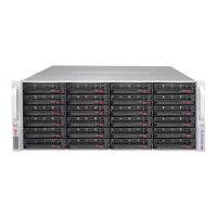
Overview of chassis features, HDD bays, power, and cooling.
Link to Supermicro website for shipping lists and part numbers.
Recommends purchasing parts from authorized Supermicro distributors/resellers.
Provides contact information for Supermicro headquarters, Europe, and Asia-Pacific.
Outlines the process for obtaining warranty service and returning merchandise.
Provides a quick setup checklist assuming experienced technician.
Advises inspecting chassis for damage and choosing a suitable location.
Mentions rail assemblies and mounting screws for rack installation.
Basic electrical safety measures to protect against harm and equipment damage.
Precautions regarding cleanliness, clothing, jewelry, and securing the system.
Discusses electrostatic discharge (ESD) and measures to protect equipment.
Describes LEDs on the control panel and drive carriers for system status.
Details the function of the power on/off and reset buttons on the chassis.
Explains the meaning of control panel LEDs like Power, HDD, NIC1, NIC2, Overheat/Fan Fail.
Describes the blue and red LEDs on SAS/SATA drive carriers indicating status.
Covers component installation and maintenance, requiring a Phillips screwdriver.
Provides steps and a warning about operating the server without the cover.
Details the process of removing and installing hard drive carriers.
Explains installing 3.5" and 2.5" fixed hard drives using brackets.
Steps for installing the motherboard, including standoffs and securing screws.
Information on installing expansion cards in LP and UIO chassis configurations.
Instructions for installing the air shroud to concentrate airflow for fan efficiency.
Guidance on ensuring proper airflow by removing obstructions.
Details on replacing system fans, including procedures and diagrams.
Information on the 1400 Watt redundant power supply and how to change it.
Provides a quick setup checklist for getting the chassis up and running in a rack.
Guidance on unpacking, inspecting for damage, and selecting a suitable rack location.
Details rack rail assemblies, screws, and converter brackets for rack mounting.
Safety warnings and precautions related to rack installations and general server handling.
Factors to consider for rack mounting, including temperature, airflow, and grounding.
Step-by-step instructions for installing the chassis into a rack using rail assemblies.
Lists supported cables for the chassis system and where to find more information.
Lists specific cable part numbers, types, lengths, and descriptions.
Describes compatible SAS/SATA cables and alternate cable options.
Lists and describes common screws used for chassis setup.
Lists the specifications for the 1400W power supply, including AC input and DC output.
Safety guidelines for handling electronic components to prevent ESD damage.
General safety advice for working with the SAS-826A backplane and system.
A note regarding images and layouts potentially differing from received hardware.
Introduces the SAS-826A backplane technology and manual revision.
Identifies and describes front connectors and jumper locations on the backplane.
Details pin definitions for activity LED headers, I2C connectors, and chips.
Explains jumper operation and lists specific jumper settings for chip resets.
Identifies rear SAS/SATA connectors and their corresponding LED indicators.
Safety guidelines for handling electronic components to prevent ESD damage.
General safety advice for working with the SAS-846A backplane and system.
A note regarding images and layouts potentially differing from received hardware.
Introduces the SAS-846A backplane technology and manual revision.
Identifies and describes front connectors and components on the backplane.
Details pin definitions for MG9072 chip, upgrade connectors, and power connectors.
Explains jumper operation and lists specific jumper settings for chip resets.
Identifies rear SAS/SATA connectors and their corresponding LED indicators.
Safety guidelines for handling electronic components to prevent ESD damage.
General safety advice for working with the SAS-826EL backplane and system.
A note regarding images and layouts potentially differing from received hardware.
Introduces the SAS-826EL backplane technology and manual revision.
Identifies and describes front connectors and components on the backplane.
Details pin definitions for I2C connectors, power connectors, and fan connectors.
Explains jumper operation and lists general jumper and socket settings.
Identifies rear SAS/SATA connectors and their corresponding LED indicators.
Describes single and dual port expanders and their support for cascading.
Explains failover mechanisms for single and dual host bus adapter configurations.
Describes the JBPWR2 power card and its use in JBOD configurations.
Lists common cables for connecting internal HBAs to the backplane.
Details cables for connecting internal HBAs, including iPass and SFF-8087/SFF-8088 types.
Describes connecting external HBAs for JBOD configurations using CBL-0200L cable.
Explains cabling for cascading multiple backplanes from a single HBA.
Explains cabling for cascading multiple backplanes from dual HBAs.
Details cascading configurations, including requirements for HBAs and power cards.
Illustrates dual SAS HBA and cascading configurations with multiple power cards.
Shows cascaded configurations with horizontal branching for single SAS HBAs.
Illustrates dual SAS HBA cascaded configurations with branching.
Safety guidelines for handling electronic components to prevent ESD damage.
General safety advice for working with the SAS-846EL backplane and system.
A note regarding images and layouts potentially differing from received hardware.
Introduces the SAS-846EL backplane technology and manual revision.
Identifies and describes front connectors and jumpers on the backplane.
Details pin definitions for I2C connectors, power connectors, and fan connectors.
Explains jumper operation and lists general jumper and socket settings.
Identifies rear SAS/SATA connectors and their corresponding LED indicators.
Describes single and dual port expanders and their support for cascading.
Explains failover mechanisms for single and dual host bus adapter configurations.
Describes the JBPWR2 power card and its use in JBOD configurations.
Lists common cables for connecting internal HBAs to the backplane.
Details cables for connecting internal HBAs, including iPass and SFF-8087/SFF-8088 types.
Describes connecting external HBAs for JBOD configurations using CBL-0200L cable.
Explains cabling for cascading multiple backplanes from a single HBA.
Explains cabling for cascading multiple backplanes from dual HBAs.
Details cascading configurations, including requirements for HBAs and power cards.
Shows cascaded configurations with horizontal branching for single SAS HBAs.
Illustrates dual SAS HBA and cascading configurations with multiple power cards.
Illustrates dual SAS HBA cascaded configurations with branching.