2-8
X8DTH-6/X8DTH-6F/X8DTH-i/X8DTH-iF User's Manual
Note: Memory speed support depends on the CPU used on the moth-
erboard.
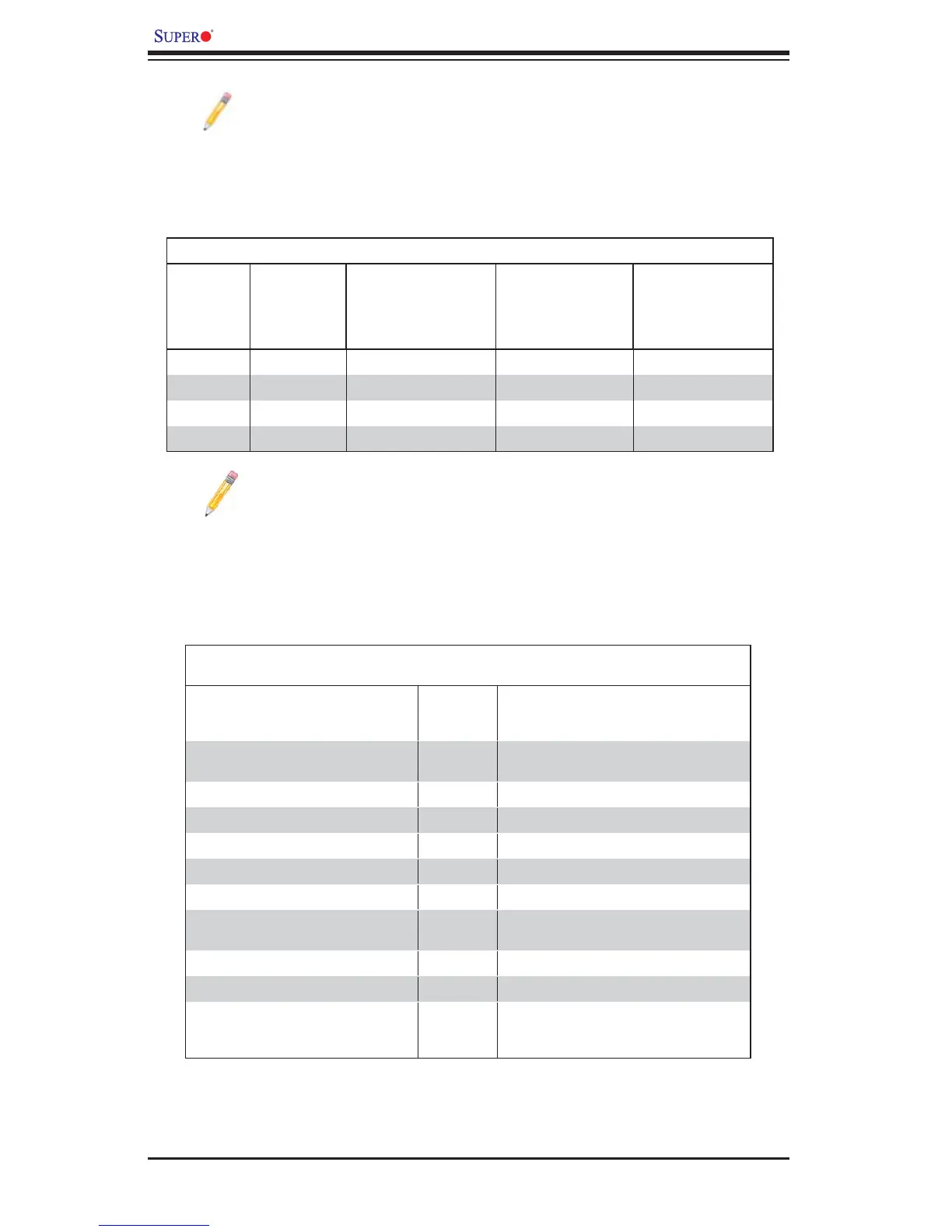
DIMM Module Population Confi guration
For memory to work properly, follow the tables below for memory installation:
DIMM Population Table
DIMM
Slots per
Channel
DIMMs
Populated
per Channel
DIMM Type (FBD=
Fully Buffered)
Speeds (in MHz) Ranks per DIMM
(any combination;
SR=Single Rank,
DR=Dual Rank,
QR=Quad Rank)
2 1 FBD DDR3 ECC 1066,1333 SR, DR
2 1 FBD DDR3 ECC 1066, QR
2 2 FBD DDR3 ECC 1066,1333 SR, DR
2 2 FBD DDR3 ECC 1066 SR, DR, QR
Note 1: Due to OS limitations, some operating systems may not show
more than 4 GB of memory.
Note 2: Due to memory allocation to system devices, the amount of
memory that remains available for operational use will be reduced when
4 GB of RAM is used. The reduction in memory availability is dispropor-
tional. (See the following Memory Availability Table.)
Possible System Memory Allocation & Availability
System Device Size Physical Memory
Remaining (-Available) (4 GB Total System
Memory)
Firmware Hub fl ash memory (System
BIOS)
1 MB 3.99 GB
Local APIC 4 KB 3.99 GB
Area Reserved for the chipset 2 MB 3.99 GB
I/O APIC (4 Kbytes) 4 KB 3.99 GB
PCI Enumeration Area 1 256 MB 3.76 GB
PCI Express (256 MB) 256 MB 3.51 GB
PCI Enumeration Area 2 (if needed)
-Aligned on 256-MB boundary-
512 MB 3.01 GB
VGA Memory 16 MB 2.85 GB
TSEG 1 MB 2.84 GB
Memory available for the OS & other
applications
2.84 GB