Chapter 2: Installation
2-25
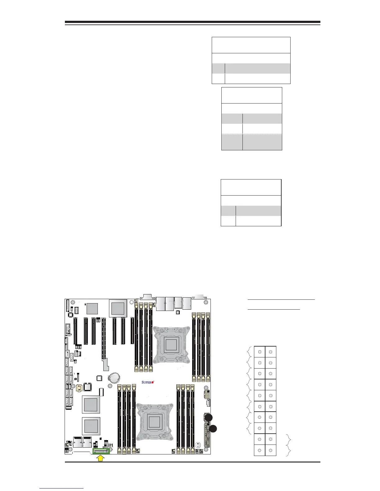
Power Button
OH/Fan Fail LED
1
NIC1 LED
Reset Button
2
HDD LED
Power LED
Reset
PWR
Vcc
Vcc
Vcc
Vcc
Ground
Ground
1920
Vcc
X
Ground
NMI
X
Vcc
PWR Fail LED
NIC2 LED
X9DRH-7F/iF/iF-NV/7TF/iTF
Rev. 1.02
B
Power Fail LED
The Power Fail LED connection is
located on pins 5 and 6 of JF1. Re-
fer to the table on the right for pin
denitions.
PWR Fail LED
PinDenitions(JF1)
Pin# Denition
5 3.3V
6 PWR Supply Fail
A
A. OH/Fail/PWR Fail LED
B. PWR Supply Fail
Overheat (OH)/Fan Fail LED
Connect an LED cable to pins 7 and 8
of JF1 to provide advanced warnings
of chassis overheating and fan failure.
Refer to the table on the right for pin
denitions.
OH/Fan Fail/PWR Fail LED
PinDenitions(JF1)
Pin# Denition
7 Vcc
8 OH/Fan Fail LED)
OH/Fan Fail Indicator
Status
State Denition
Off Normal
On Overheat
Flash-
ing
Fan Fail

 Loading...


