FP CTRL
JPS1
LEDS1
FAN4
FAN3
USB4/5
USB6
USB8/9
T-SGPIO-S
JPME2
JPME1
A
B
C
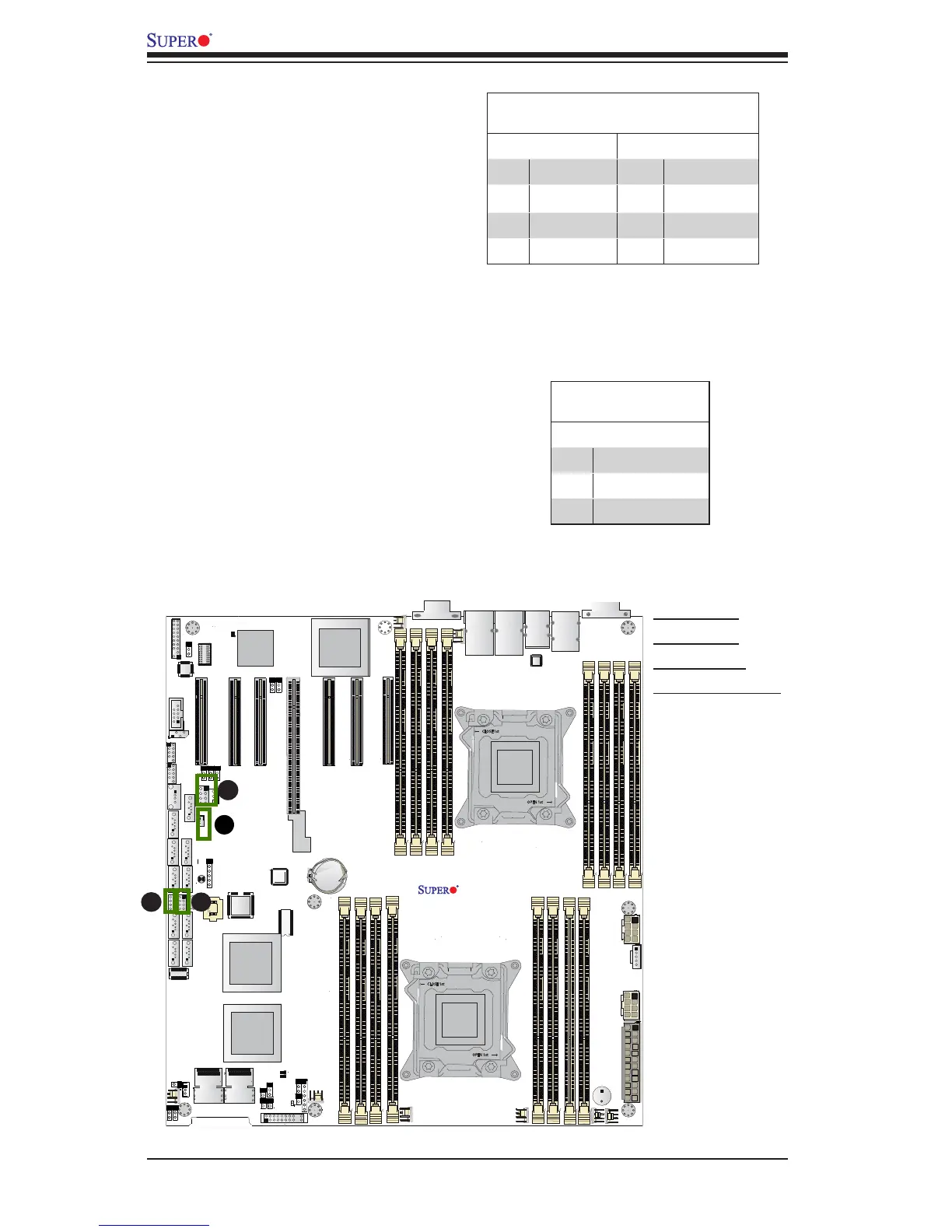
A. T-SGPIO1
B. T-SGPIO2
C. T-SGPIO-S
D. SATA DOM PWR
T-SGPIO1/2/T-SGPIO-S Headers
Two SGPIO (Serial Link General
Purpose Input/Output) headers are
located at T-SGPIO1/2 on the moth-
erboard to support I-SATA 0~5 ports.
Additionally, T-SGPIO-S supports S-
SATA 0~3 ports. These headers sup-
port Serial Link interface for onboard
SATA connections. See the table on
the right for pin denitions.
Note: NC= No Connection
T-SGPIO
PinDenitions
Pin# Denition Pin Denition
1 NC 2 NC
3 Ground 4 Data
5 Load 6 Ground
7 Clock 8 NC
SATA DOM Power Connector
A power connector for SATA DOM
(Disk_On_Module) devices is located
at JSD1. Connect an appropriate
cable here to provide power support
for your SATA DOM devices.
DOM PWR
PinDenitions
Pin# Denition
1 +5V
2 Ground
3 Ground